1. FFT Gyro Components
1.1 Component Nomenclature
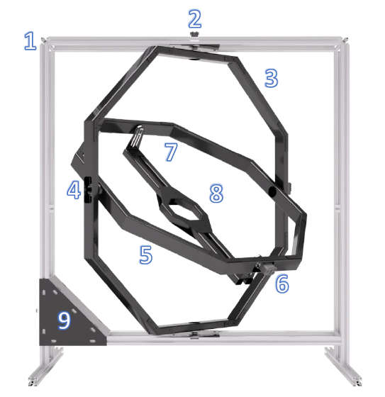
The FFT GYRO resembles the structure of a typical gyroscope with three degrees of freedom (3 DOF). The main components of the FFT GYRO listed below.
| Number | Component |
|---|---|
| 1 | Base structure (F1) |
| 2 | Angular sensor “Yaw” (S1) |
| 3 | Octagonal structure – Yaw gimbal (G1) |
| 4 | Angular sensor “Pitch” (S2) |
| 5 | Octagonal structure – Pitch gimbal (G2) |
| 6 | Angular sensor “Roll” (S3) |
| 7 | Sliding structure – Roll gimbal (G3) |
| 8 | Multi-rotor base (B1) |
| 9 | Electronic board FFT Gyroboard |
1.2 Component Description
This section aims to provide a clear understanding of the FFT GYRO system by describing its main components. We'll use the specific names listed in the table above to refer to each component, ensuring consistency throughout the user guide.
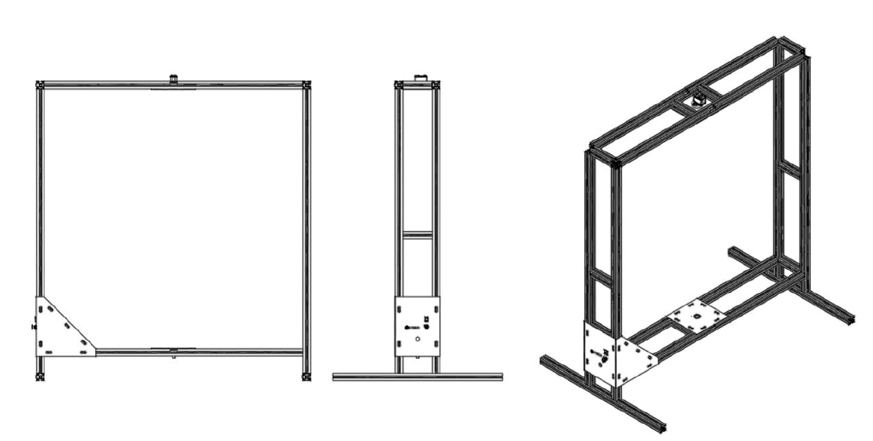
1.2.1 Base Structure
- The base structure (F1) is designed to provide structural support to the entire system.
- This supporting assembly is composed of aluminum plates and profiles; this grants the system desired properties such as corrosion resistance and a light but strong structure.
- The structure delimits the space in which the multi-rotor will move, thus bringing safety to the user and the equipment.
- In case of more safety requirements, a protection fence can be attached to the aluminum profiles of the structure.
Note
- The protection fence is not part of the FFT Gyro system and is sold separately.
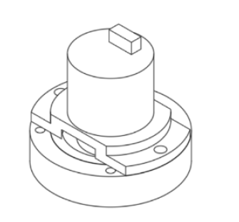
1.2.2 Angular Position Sensors
- The platform has three angular sensors with the purpose of measuring the three degrees of freedom of the system: Roll (S3), Pitch ((S2)) and Yaw *(S1)*.
- The angular sensors (or encoders) are of magnetic type; they do not add friction to the system since there are no pieces in contact.
- The encoders are also of absolute type and multi-spin; the system can measure with high precision (12 bits) while the multi-rotor spins freely in any direction.
- These components are of reduced size and weight to ensure that the extra inertia that the system adds to the multi-rotor is minimal.
- The encoders can be replaced by servomotors* to generate external forces to the multi-rotor, simulating disturbances like wind or turbulence.
- The motors cannot be installed simultaneously with the encoders; they are interchangeable with each other. Either there are three encoders or three motors, there is no intermediate configuration.
- When the encoders are installed, the system has extremely low friction or free movement. This configuration is exceptionally good for evaluating the dynamics of the aircraft, calibrating controllers, or simulating as if the drone is flying freely.
- When the motors are installed, the system does not have free movement, as the motors have a gear train that adds a considerable load to the system.
- This configuration is ideal for evaluating the robustness of the controllers in the presence of external forces, which are simulated by the motors themselves.
- The sensors and actuators are connected through an internal wiring system to the FFT Gyroboard card, which has special firmware and drivers to communicate to a PC via USB.
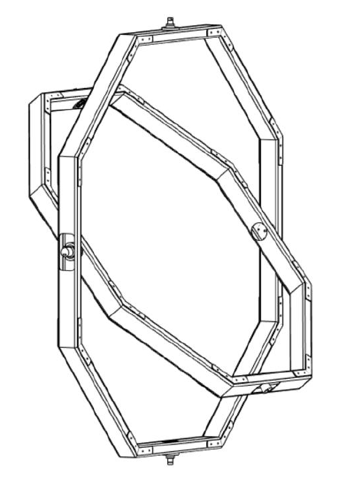
1.2.3 Octagonal structures: Yaw gimbal and Pitch gimbal
- The octagonal structures are designed to maximize the structural strength of the system while maintaining the less weight possible.
- These components are built with high-impact aluminum and carbon fiber machined parts.
- The encoders can be replaced by servomotors* to generate external forces to the multi-rotor, simulating disturbances like wind or turbulence.
- The motors cannot be installed simultaneously with the encoders; they are interchangeable with each other. Either there are three encoders or three motors, there is no intermediate configuration.
- When the encoders are installed, the system has extremely low friction or free movement. This configuration is exceptionally good for evaluating the dynamics of the aircraft, calibrating controllers, or simulating as if the drone is flying freely.
- When the motors are installed, the system does not have free movement, as the motors have a gear train that adds a considerable load to the system.
- This configuration is ideal for evaluating the robustness of the controllers in the presence of external forces, which are simulated by the motors themselves.
- The sensors and actuators are connected through an internal wiring system to the FFT Gyroboard card, which has special firmware and drivers to communicate to a PC via USB.
- The Pitch gimbal (G2) is clamped to (G1) in the same way that (G1) is clamped to (F1), but this junction uses the (S2) sensor to measure the Pitch angle.
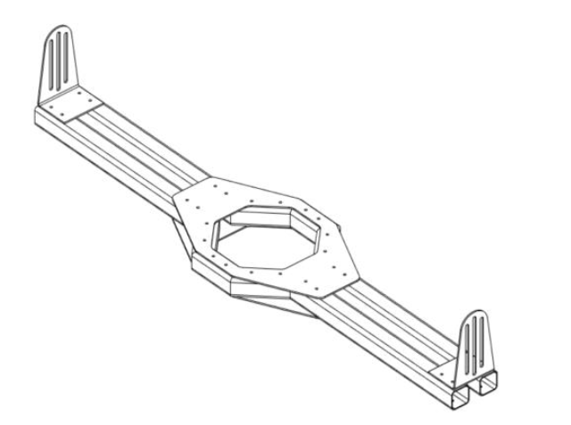
1.2.4 Multi-rotor base: Roll gimbal
- The base B1 (referred as Roll gimbal) is designed to support several types of multi-rotors, both in configuration and size, and allow them to rotate in reference to their axis.
- The roll base is made of either aluminum or carbon fiber and is attached to two sliding structures connected to the circular structure by rotary joints.
- The sliding structure (G3) helps adjust the height of the platform where the multi-rotor is held to align the rotation center of the multi-rotor with the rotation center of the FFT GYRO system.
- In one of these joints, the sensor S3 is located, to measure the Roll angle, while in the opposite end a slip-ring allows the communication of six electric channels for the user to use freely, according to their needs.
1.2.5 FFT Gyroboard
- The FFT GYRO system is composed of three angular position sensors (replaceable by servomotors) connected to the data acquisition board via USB as a communication interface with the PC.
- This data acquisition board is the FFT Gyroboard.
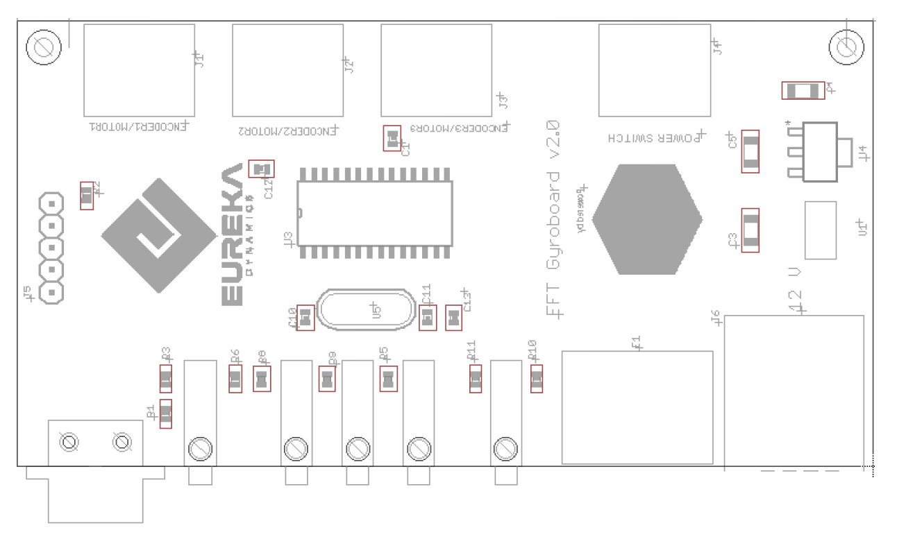
- The system can be used with an open-source, multi-platform and very simple interface called FFT GYRO Test Tool.
- To download, visit https://gitlab.com/eurekadynamics/fft-gyro
- MATLAB/Simulink programs are also included in the FFT GYRO system, for reading and writing of the encoders and motors.
Note
- For customized application development, please refer to the communication protocol section.
1.3 Dimensions and main parameters
- This section discusses main dimensions, and parameters of the FFT GYRO system.
- Dimensions are expressed using the International System of Units (SI).
- The FFT GYRO system is built using anodized aluminum or carbon fiber parts.
- These materials make the structure rigid & safe enough to support the drone weight and light enough to minimize the external weight effects on the performance of the UAV.
- Keeping in view the variable drone sizes, FFT GYRO comes in different sizes and configurations.
- Each size category of FFT Gyro, is capable to support drones belonging to the same size and weight category
- Aligned with the typical commercial drone measurements, FFT Gyro comes in the following size series.
- Series 250
- Series 450
- Series 600
- Principal dimensions and parameters of each size series are explained below.
1.3.1 Series 250
- Series 250 has been designed for small drones, with a rotor-to-rotor distance of 250 mm (maximum) plus typical propellers diameter of 153 mm (6”).
- The recommended drone sizes for Series 250 are;
- Drones having rotor-to-rotor distance of 100 mm to 250 mm
- Drones with a maximum external diameter of 450 mm (including propellers).
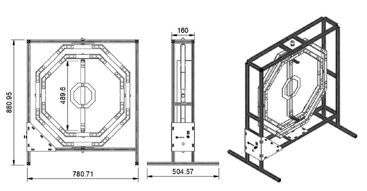
- The table below lists the principal mechanical parameters of this series.
| Parameter | Specification / Value |
|---|---|
| Dimensions – L x W x H | 785 mm x 505 mm x 896 mm. |
| Device mass | 7256 grams. |
| Encoder’s resolution | 0.0879° (12-bits). |
| Base G3 (roll) mass and inertia | 200 g – 3.58E+05 g-mm2 (on the rotation axis) |
| Gimbal G2 (pitch) mass and inertia | 610 g – 2.37E+07 g-mm2 (on the rotation axis). |
| Gimbal G1 (yaw) mass and inertia | 670 g – 3.52E+07 g-mm2 (on the rotation axis). |
| Roll, pitch, and yaw range | 360° (multi-roll). |
| Compatible multi-rotor sizes | From 100mm to 250mm rotor-to-rotor distance OR up to 450 mm OD with propellers |
| Power specifications | 12 VDC, 5 A, 120W. |
| Communication protocols | USB2.0, serial port, acquisition rate of 100 Hz. |
1.3.2 Series 450
- Series 450 has been designed for small-medium sized drones, with a rotor-to-rotor distance of 450 mm (maximum) plus typical propellers diameter of 254 mm (10”).
- The recommended drone sizes for Series 450 are;
- Drones having rotor-to-rotor distance of 250 mm to 450 mm.
- Drones with a maximum external diameter of 750 mm (including propellers).
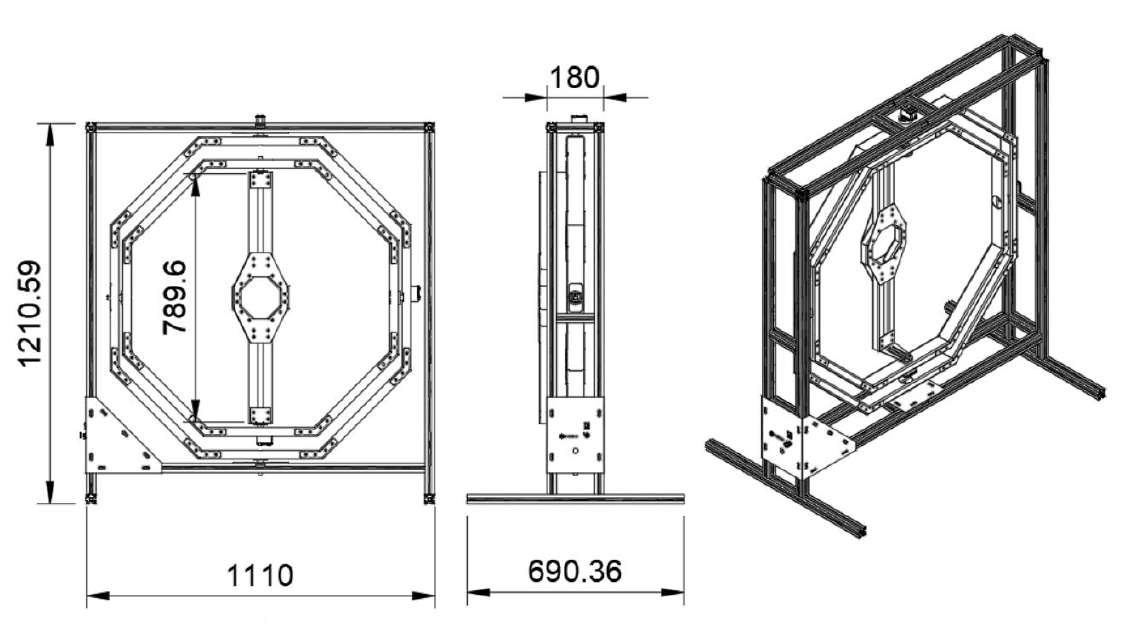
- The table below lists the principal mechanical parameters of this series.
| Parameter | Specification / Value |
|---|---|
| Dimensions – L x W x H | 1132 mm x 691 mm x 1237 mm. |
| Device mass | 19,000 grams. |
| Encoder’s resolution | 0.0879° (12-bits). |
| Motor Power | 1530 g/mm (15.3 Kg/cm). |
| Base G3 (roll) mass and inertia | 660 g – 1.83E+06 g-mm2 (on the rotation axis) |
| Gimbal G2 (pitch) mass and inertia | 1250 g – 1.17E+08 g-mm2 (on the rotation axis). |
| Gimbal G1 (yaw) mass and inertia | 1350 g – 1.56E+08 g-mm2 (on the rotation axis). |
| Roll, pitch, and yaw range | 360° (multi-roll). |
| Compatible multi-rotor sizes | From 250mm to 450mm rotor-to-rotor distance OR up to 750 mm OD with propellers |
| Power specifications | 12 VDC, 5 A, 120W. |
| Communication protocols | USB2.0, serial port, acquisition rate of 100 Hz. |
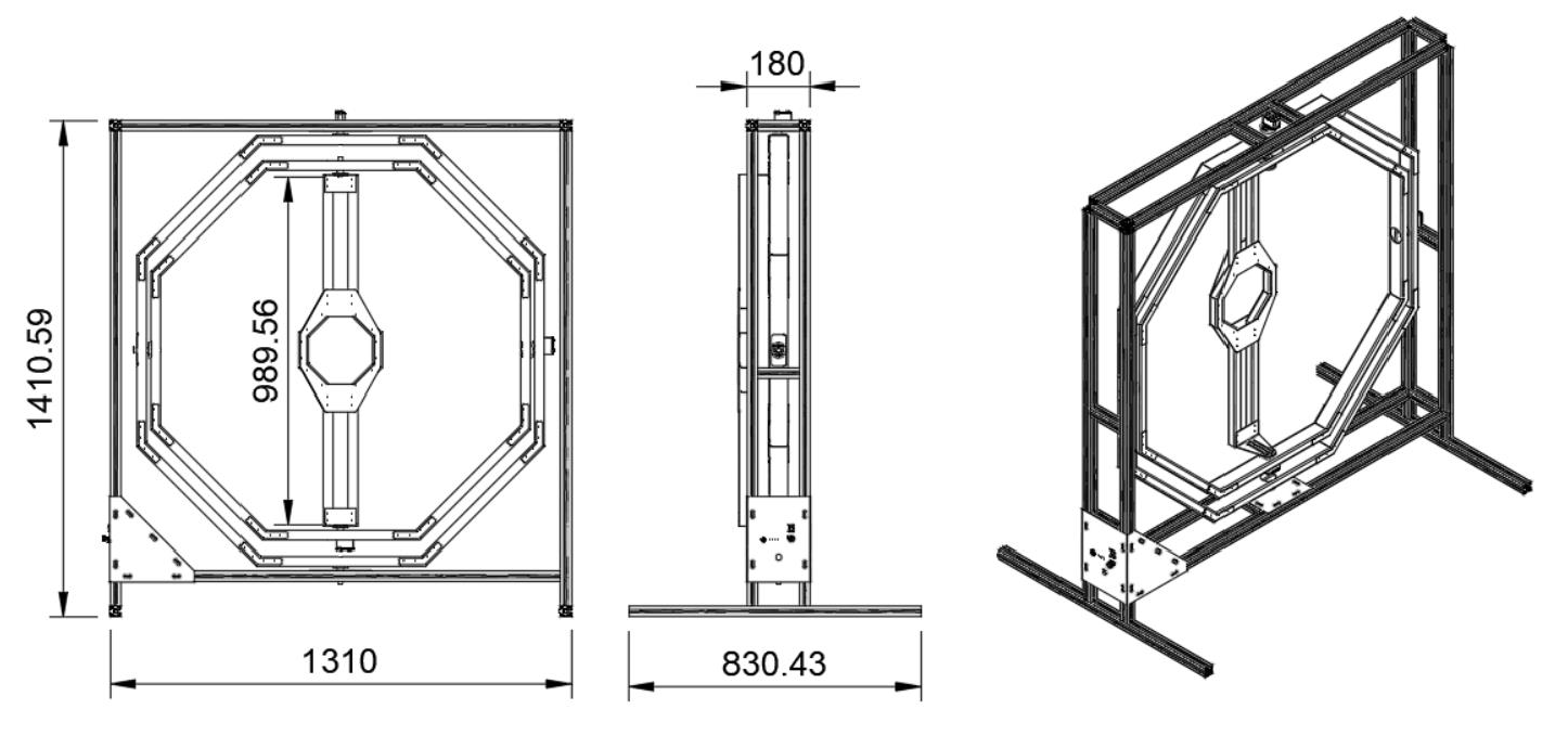
1.3.3 Series 600
- Series 450 has been designed for medium sized drones, with a rotor-to-rotor distance of 6000 mm (maximum) plus typical propellers diameter of 305 mm (12”).
- The recommended drone sizes for Series 600 are;
- Drones having rotor-to-rotor distance of 450 mm to 600 mm.
- Drones with a maximum external diameter of 950 mm (including propellers).
- The table below lists the principal mechanical parameters of this series.
| Parameter | Specification / Value |
|---|---|
| Dimensions – L x W x H | 1132 mm x 691 mm x 1437 mm. |
| Device mass | 20,500 grams. |
| Encoder’s resolution | 0.0879° (12-bits). |
| Motor Power | 1530 g/mm (15.3 Kg/cm). |
| Base G3 (roll) mass and inertia | 850 g – 3.58E+06 g-mm2 (on the rotation axis) |
| Gimbal G2 (pitch) mass and inertia | 1450 g – 2.05E+08 g-mm2 (on the rotation axis). |
| Gimbal G1 (yaw) mass and inertia | 1550 g – 2.60E+08 g-mm2 (on the rotation axis). |
| Roll, pitch, and yaw range | 360° (multi-roll). |
| Compatible multi-rotor sizes | From 450mm to 600mm rotor-to-rotor distance OR up to 950 mm OD with propellers |
| Power specifications | 12 VDC, 5 A, 120W. |
| Communication protocols | USB2.0, serial port, acquisition rate of 100 Hz. |