4. FFT GYRO BOARD Technical Specifications
The FFT GYRO BOARD is the heart of the whole system and is responsible for real time communication & control of the onboard Drone. This section explains the technical specifications of the FFT GYRO BOARD.
4.1 FFT GYRO BOARD Specifications
- The table below lists the principal technical parameters of the FFT GYRO BOARD.
FFT GYRO BOARD Specifications
-
Sensors:
-
Absolute Magnetic Encoders
- 5 Volts
- 12 bit Resolution
-
Digital motor capable of reading applied torque (12 V Operation)
- SSI Interface
- 10-bit resolution to measure torque
-
-
40 MHZ Clock System
-
Updatable firmware
-
Protocol USB 2.0 (USB Mini B)
-
Auto select mode
- The system automatically selects the mode of operation when three sensors of the same kind are connected.
-
12-15 DC volts operation with external energy source
-
PCB size: 9.8 x 5.1 cm
-
Fuse protection of 2 Amp
-
Variable sensor sampling
- 10 milliseconds to 2.5 seconds (Default: 10 ms, steps of 10 ms)
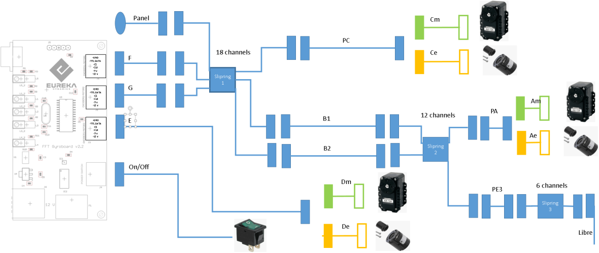
4.2 Schematic Diagram
Below is the schematic diagram of the FFT GYRO BOARD
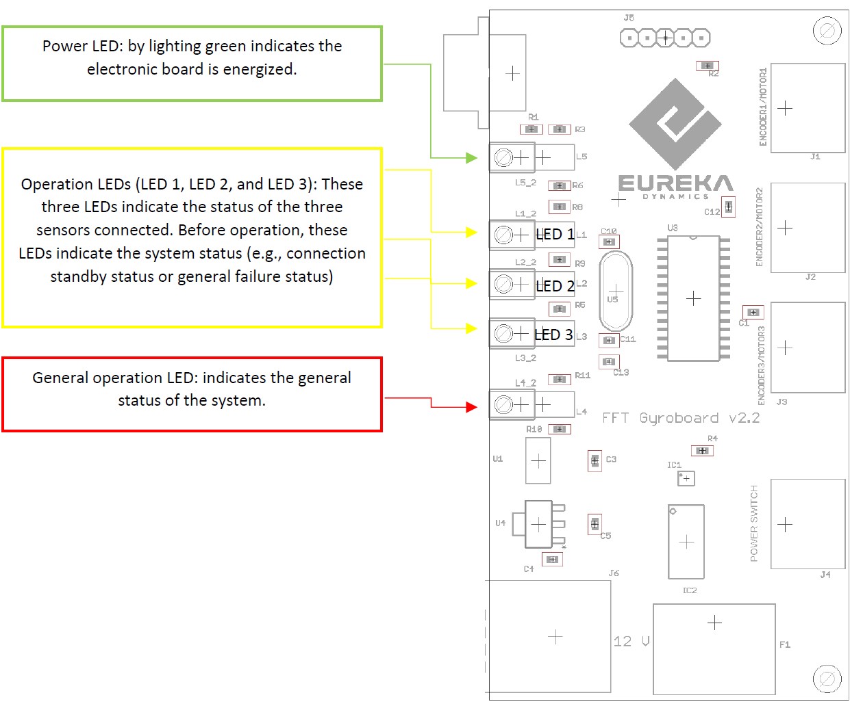
4.3 Description of the LEDs
The figure below mentions where the status LEDs are located and what each LED indicates.
4.4 LED Indications and Explanations
4.4.1 Encoder Mode
- Make sure the on-off switch is off. The system must be in off mode.
- Connect the external energy source (12 VCD) in the barrel Jack port and secure it with its thread.
- Connect the encoders with all their respective connectors (Connector A, Connector C, Connector D) to the system.
- When all the encoders are connected, turn on the System.
- Once energized, the energy LED will light up (green led).
- Now the system is ready to start the data transmission.
- Refer to the table below for LED indication explanation.
| Mode | Operation State | Power LED | Status LED (One) | Status LED (Two) | Status LED (Three) | Operations LED |
|---|---|---|---|---|---|---|
| Encode Mode | Normal | |||||
| Encode Mode | Sensor-1 Fail | |||||
| Encode Mode | Sensor-2 Fail | |||||
| Encode Mode | Sensor-3 Fail | |||||
| Encode Mode | All Sensor Fail |
4.4.2 Motor Mode
- Make sure the on-off switch is off. The system must be in off mode.
- Connect the external energy source (12 VCD) in the barrel Jack port and secure it with its thread.
- Connect the motors with all their respective connectors (Connector A, Connector C, Connector D) to the system.
- When all the motors are connected, turn on the System.
- Once energized, the energy LED will light up (green led).
- Now the system is ready to start the data transmission.
- Refer to the table below for LED indication explanation.
| Mode | Operation State | Power LED | Status LED (One) | Status LED (Two) | Status LED (Three) | Operations LED |
|---|---|---|---|---|---|---|
| Motor Mode | Normal | |||||
| Motor Mode | Motor-1 Fail | |||||
| Motor Mode | Motor-2 Fail | |||||
| Motor Mode | Motor-3 Fail | |||||
| Motor Mode | All Motor Fail |
4.4.3 Connection Standby Mode
- Standby mode indicates that the system is waiting for connection with the PC.
- Refer to the table below for LED indication explanation.
| Mode | Power LED | Status LED (One) | Status LED (Two) | Status LED (Three) | Operations LED |
|---|---|---|---|---|---|
| Connection Standby Mode |
4.4.4 General Failure Mode
- Standby mode indicates that the system is waiting for connection with the PC.
- Refer to the table below for LED indication explanation.
| Mode | Power LED | Status LED (One) | Status LED (Two) | Status LED (Three) | Operations LED |
|---|---|---|---|---|---|
| General Failure Mode | |||||
| General Failure Mode | |||||
| General Failure Mode |
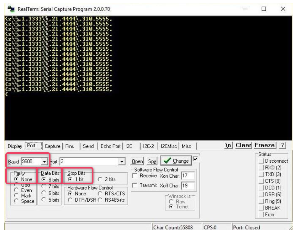
4.4 Serial Communication Specifications
Please set the following serial parameters to start the serial communication with the FFT GYROBOARD.
| Specification | Value to Set |
|---|---|
| Baud Rate | 9600 |
| Data Bits | 8 Bits |
| Parity | None |
| Stop Bits | 1 Bit |
- The screen below shows RealTerm interface which is receiving data in the Encoder Mode.