3. FFT GYRO Configurations
3.1 Software Configurations
In this section, we'll walk you through the essential steps required to download, establish a COM port connection, unzip, and install the FFT GYRO Test Tool. By following these instructions, you'll be able to easily configure the FFT GYRO Test Tool on your computer and begin interacting with your FFT GYRO hardware.
3.1.1 Download the FFT GYRO Test Tool
Eureka Dynamics has developed a user-friendly graphical interface, called FFT GYRO Test Tool, for interacting with the FFT GYRO board. This tool works seamlessly on Windows, macOS, and Linux operating systems.
- Click to download the FFT GYRO Test Tool
- Refer to the screen below, and select the correct folder for your operating system.
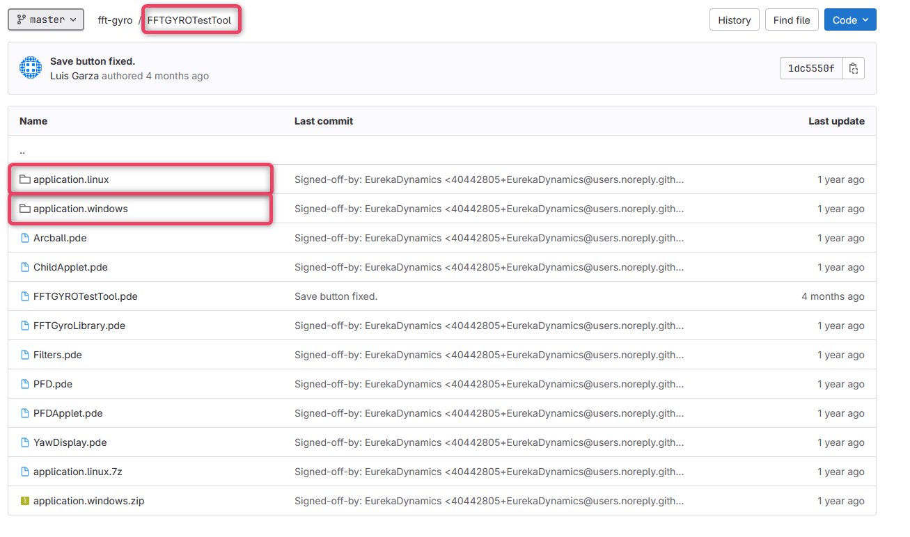
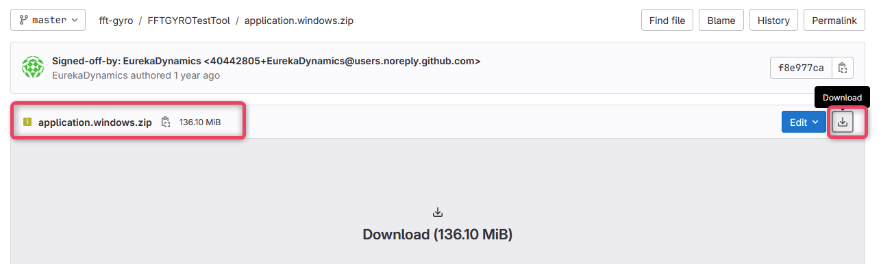
- Once inside the folder, click the download button to download the package.
- The software has minimal processing requirements due to its simple communication protocol. Requirements for the FFT GYRO Test tool are listed below:
| Requirement | Specification |
|---|---|
| Operating System | Windows 7 and above, MacOS X 10.8.5 and above, or Ubuntu Linux 12.04 or above |
| RAM | 2GB RAM (Minimum) |
| Storage | 1 GB Free Storage Space |
| USB Port | 1 USB 2.0 or higher port |
Information
- To run the FFT GYRO Test Tool as a developer, please install Processing 3.0 version or higher.
- Before running the code, also install the graphical library available in Tools/Add Tool/Library.
3.1.2 Install FFT GYRO Test Tool & Connect
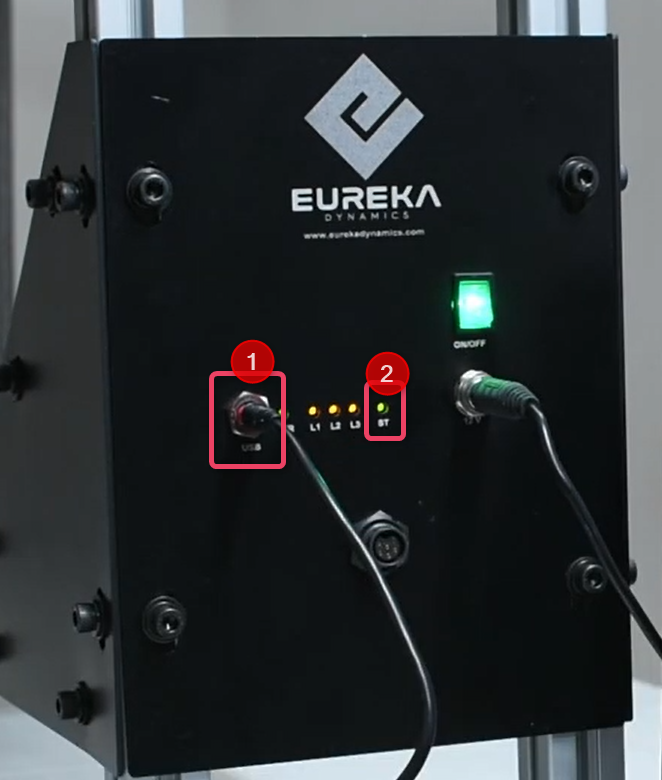
- Connect one end of the mini USD port to the FFT GYRO Board and connect the second end to the PC (which is running the FFT GYro Test Tool).
- The FFT GYRO Board will recognize the connection and the on-board LEDs will turn on to indicate the connection. Refer to the screen below for details.
- Extract the content of the archive using a standard archive tool (e.g., WinRaR or WinZip etc.).
- Navigate to the folder and locate the .exe file and double click the file to launch.
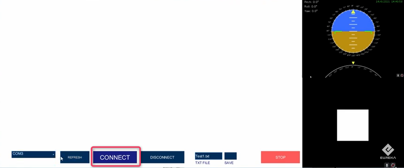
- You will see how three windows will be displayed. Locate the Main Control Window, and make sure that is totally in blank like the next image.
- Now, navigate to the FFT GYRO Test Tool screen and click the REFRESH button to update the ports available on the list.
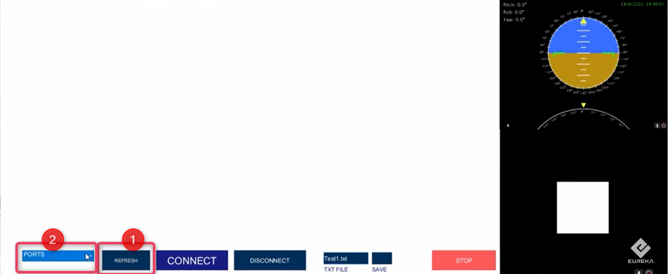
- Once the port list is shown, select the correct port. i.e., COM3 in this example.
- Click Connect.
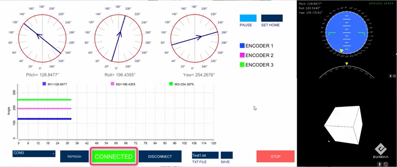
- Once a successful connection is made, the Connect button will turn to green and the label will display CONNECTED.
- The system will start receiving data from the FFT GYRO board, indicating correct connection.
3.2 Installing & Enabling Drone
Now we have the FFT GYRO setup complete and connected to the FFT Gyro Test Tool, we can install and enable the drone on the FFT GYRO setup.
3.2.1 Installing the Drone on FFT GYRO Base
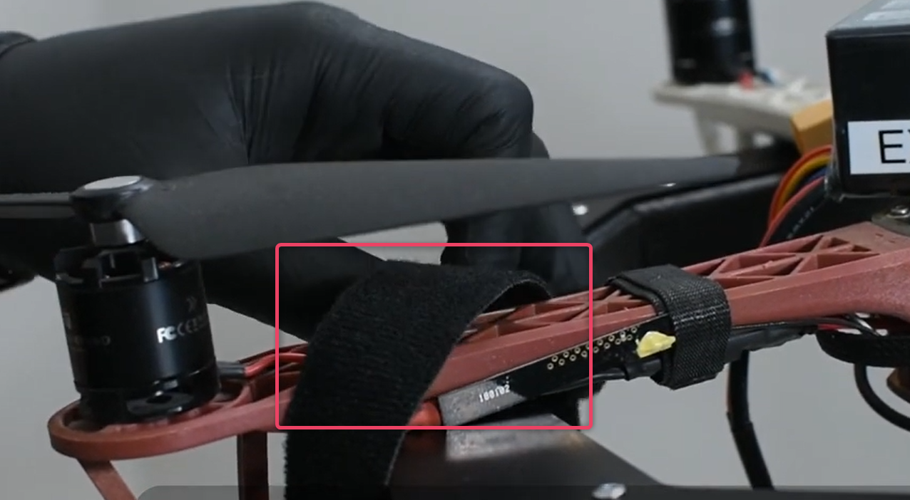
- Place the drone on the multi rotor base and secure every rotor arm to the base.
- Velcro straps can be used to secure the arms safely and easily.
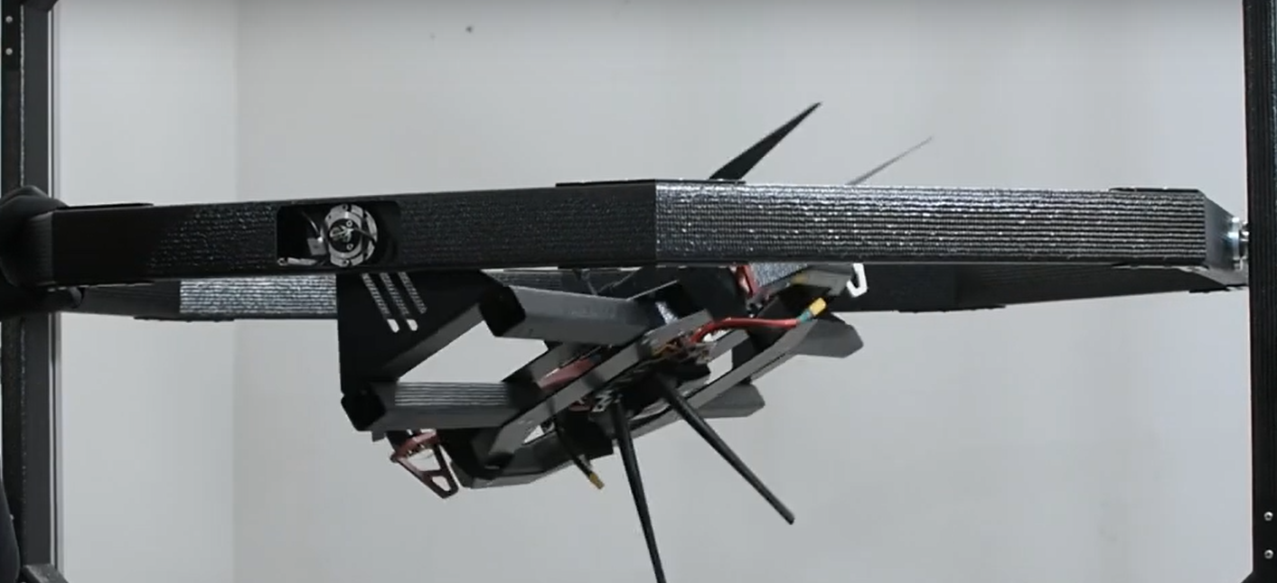
- Verify the center of mass alignment by letting the multi-rotor swing.
- After verifying that the multi-rotor is centered, align the center of mass by adjusting the height.
- This can be done using a 2.5mm key to lock the sliders in both sides.
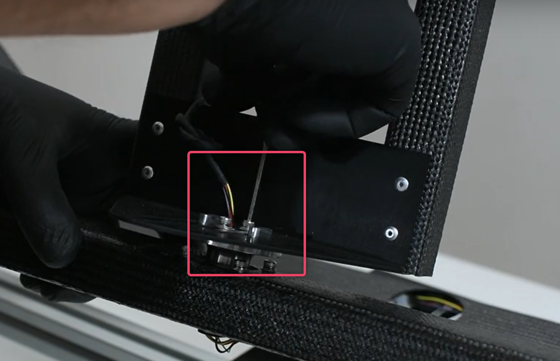
3.2.2 Sensor Calibration to Relative Zero
- Initially the encoder readings usually don’t match to onboard sensors.
- To correct the readings, turn on the multi rotor in stabilized mode.
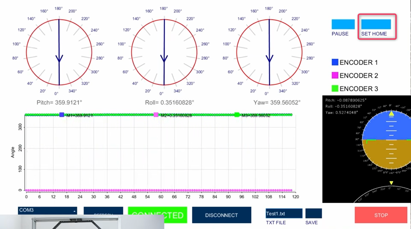
- Wait until stabilization is achieved. Once done, click the Set Home button.
3.2.3 Data Acquisition and Sensor Reading
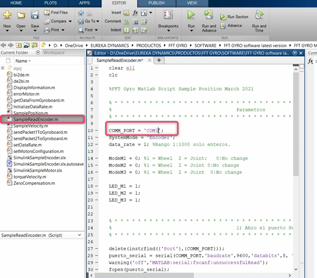
Encoder Reading in MATLAB
- For encoder readings in MATLAB open the SampleReadEncoder.m file.
- Match the communication ports. If needed, edit the port value to match your configurations.
- Now, proceed to run the script.
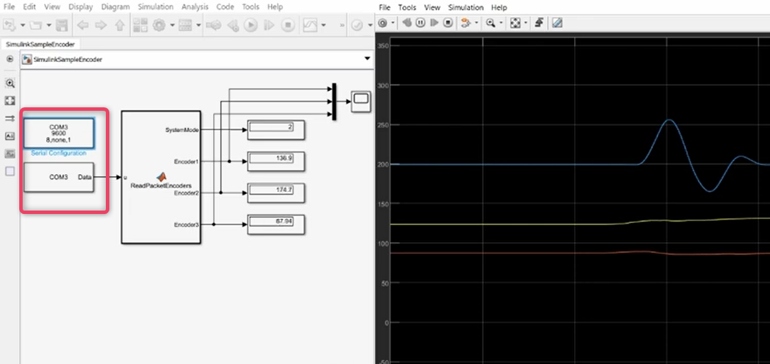
Encoder Reading in Simulink
- For encoder readings in Simulink open the SimulinkSampleEncoder.slx file.
- Configure serial configuration block to match your configurations.
- Now, proceed to run the script.
3.2.4 Motor Installation
Uninstall Encoder
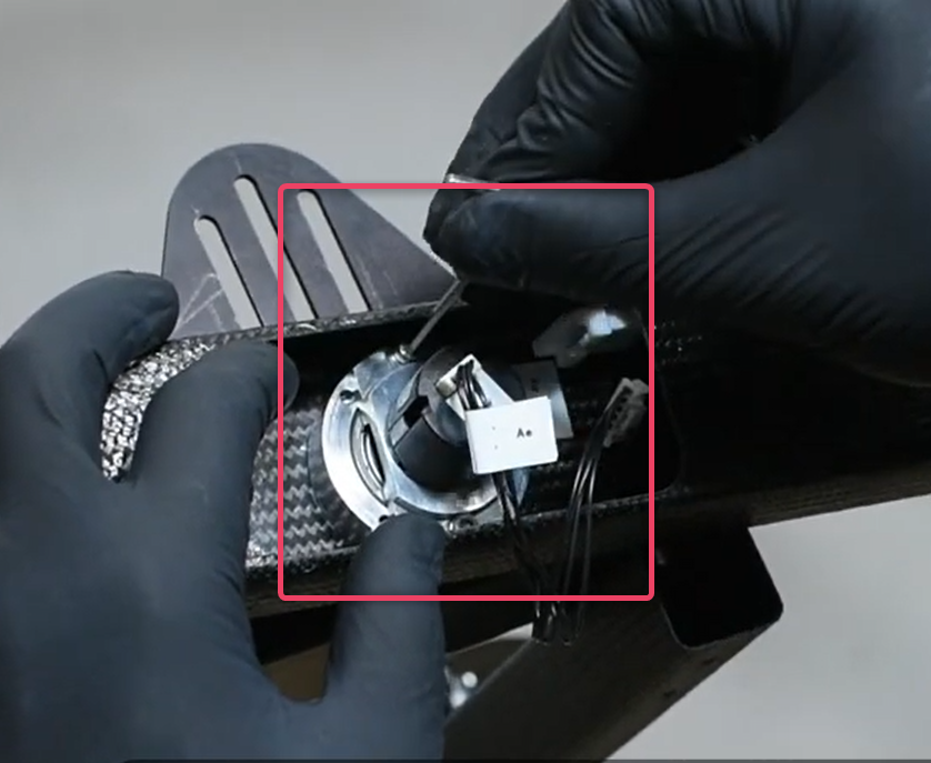
- Uninstall encoders by disconnecting the encoder cable carefully.
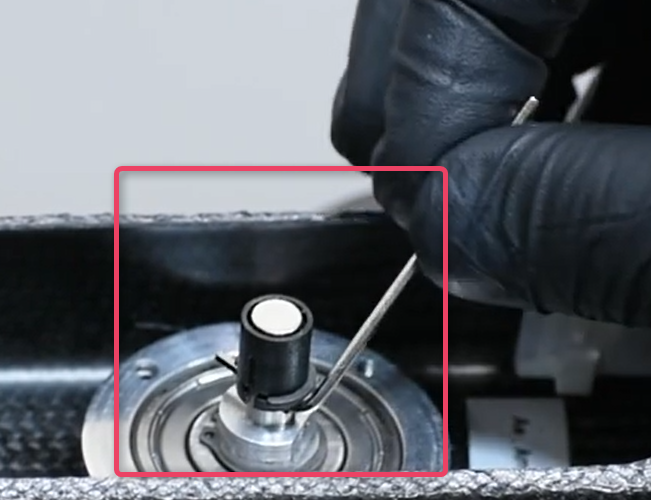
- Use a 2.5mm key to remove the encoder mount.
- Now, use a 1.5mm ley to unlock the axis.
- Repeat the same process with every encoder.
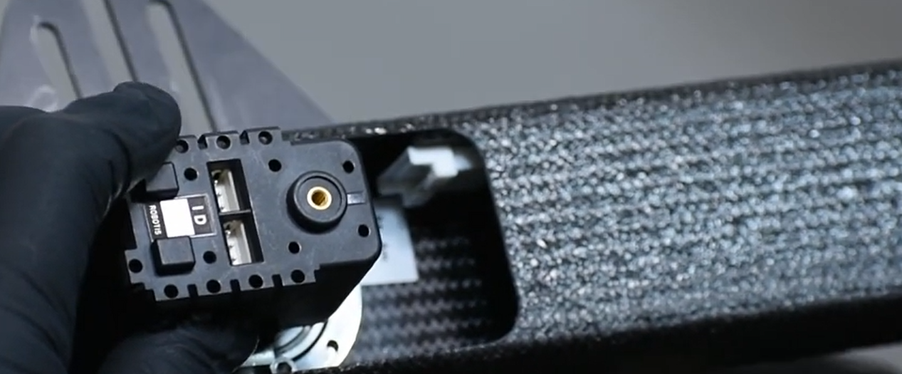
Install Motor
- Use the 2.5mm key to install the motor.
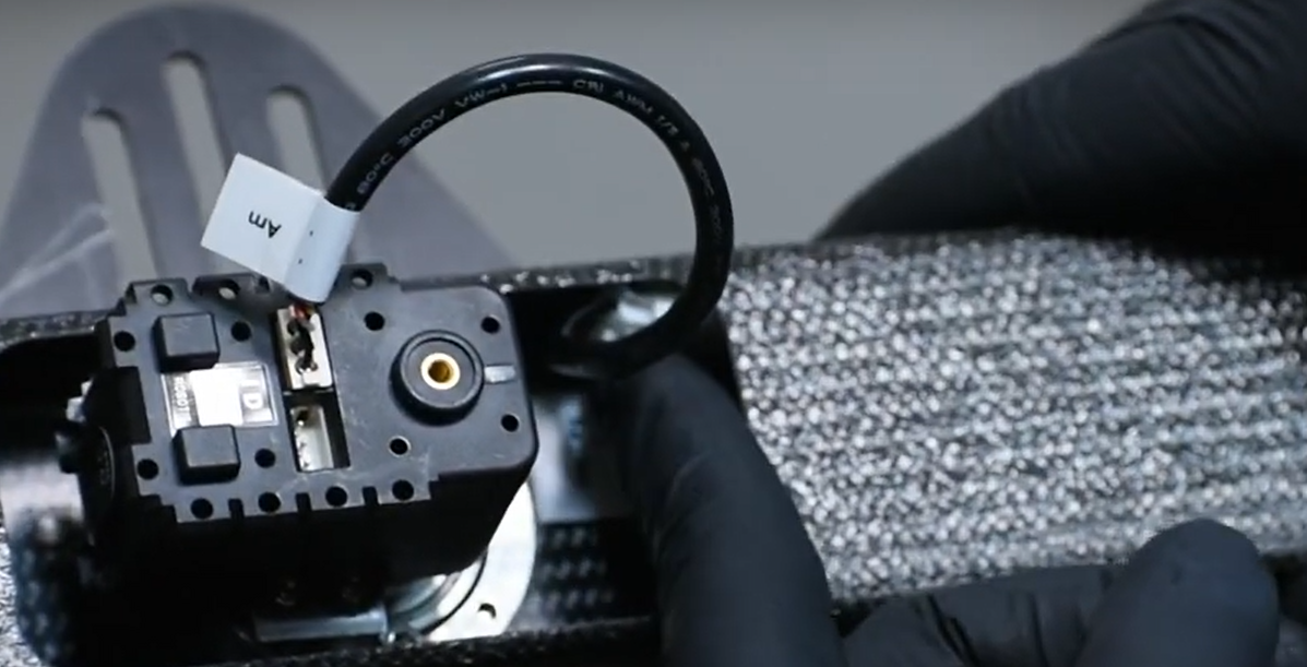
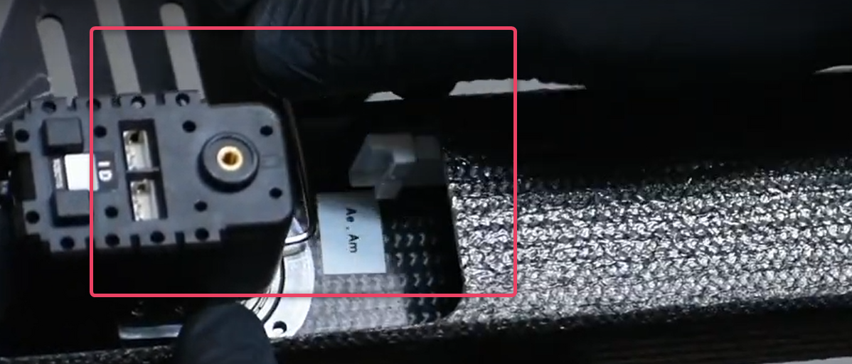
- Note the tag on the motor and the wiring.
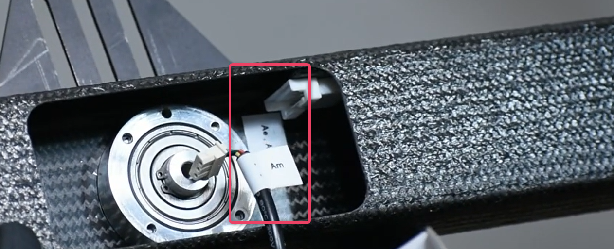
- Always install the motor in the opposite direction of the tag.
- Install the cable to complete the motor installation.
- Secure the screw tightly.
Warning
- The tag on the motor and the wiring must match. Do not install if there is a mismatch.
3.2.5 Connect Motor with FFT GYRO Test Tool
- Once motors are installed, launch the FFT GYRO Test Tool.
- Click refresh, select port, and click connect.
- Once the connection is made, you can set the configurations to the drone using the FFT GYRO Test Tool.
- To stop the motors, click the STOP button or press the Space bar.
Warning
- When motors are running, be cautious of moving high speed rotors.
Recommendation
- You can set the Torque limit as per need but it is recommended to limit the torque to 30% in the first trials.