1. FFT Gyro Components
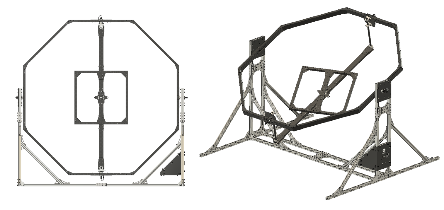
The FFT GYRO G4.0 has a similar structure to a gyroscope with three degrees of freedom (3 DOF). The main components of the FFT GYRO G4.0 are identified in Section 1.1 and described in Section 1.2.
Why the G4.0?
We are always working to improve our products based on user feedback. Some users pointed out that the yaw movement (in the G3.5 configuration), being the weakest on a drone, had too much inertia. To address this, we simplified the design in the FFT GYRO G4.0 to reduce yaw inertia by changing the order of rotation to Yaw first, then Roll, and finally Pitch (YRP). Overall, the G4.0 has less inertia, which makes it better for testing drone maneuvers. To review the differences, advantages and disadvantages between configurations G3.5 and G4.0, please review our product catalog here.
1.1 Component Nomenclature
The FFT GYRO is designed similarly to a traditional gyroscope, featuring three degrees of freedom (3 DOF). Its main components are listed below.
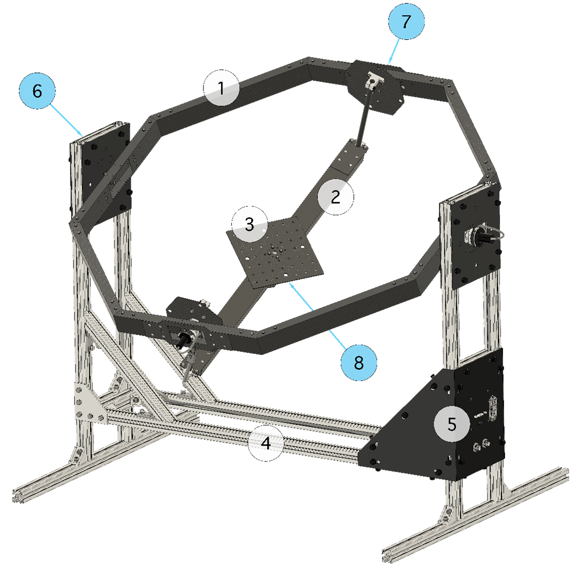
| Number | Component |
|---|---|
| 1 | Pitch gimbal |
| 2 | Roll gimbal: Sliding structure |
| 3 | Yaw gimbal: Multi-rotor base |
| 4 | Base structure |
| 5 | Electronic board: FFT Gyroboard |
| 6 | Encoder (Pitch) |
| 7 | Encoder (Roll) |
| 8 | Encoder (Yaw) |
1.2 Component Description
This section provides a clear understanding of the FFT GYRO system by describing its main components. To ensure consistency throughout the user guide, we will refer to each component using the specific names listed in the table above.
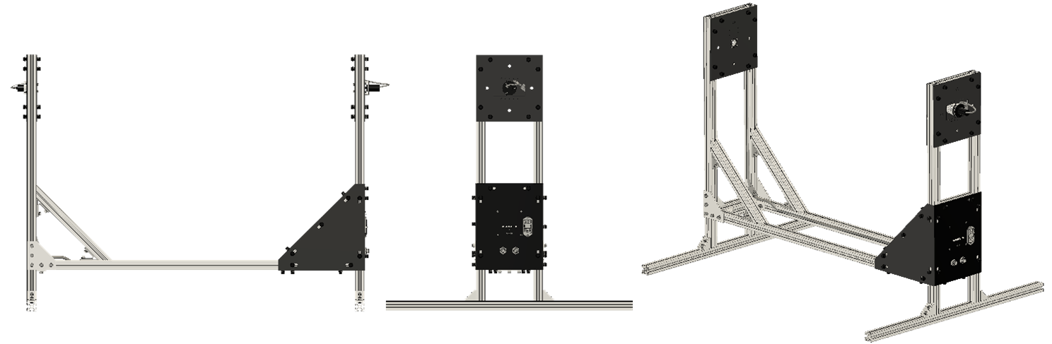
1.2.1 Base Structure
- The base structure (1) is designed to provide structural support to the entire system.
- This supporting assembly is composed of aluminum plates and profiles; this grants the system desired properties such as corrosion resistance and a light but strong structure.
- The structure delimits the space in which the multi-rotor will move, thus bringing safety to the user and the equipment.
- In case of more safety requirements, a protection fence can be attached to the aluminum profiles of the structure.
Note
- The protection fence is not part of the FFT Gyro system and is sold separately.
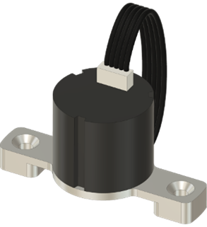
1.2.2 Encoders
- The platform is equipped with three angular sensors designed to measure the angular position of the system’s three degrees of freedom: Yaw (8), Roll (7), and Pitch (6).
- These sensors (encoders) are magnetic, eliminating friction since they operate without physical contact.
- The encoders are absolute and multi-turn, allowing the system to measure with high precision while the multi-rotor spins freely in any direction.
- Their compact size and lightweight design ensure minimal added inertia, preserving the multi-rotor’s natural dynamics.
- The encoders can be replaced with servomotors (motor kits sold separately). These smart motors have the purpose to generate external forces on the multi-rotor, simulating disturbances such as wind or turbulence.
- The motors and encoders cannot be installed simultaneously; they are interchangeable. The system can be configured with either three encoders or three motors, but not a combination of both.
- When encoders are installed, the system operates with extremely low friction, allowing free movement. This configuration is ideal for evaluating aircraft dynamics, calibrating controllers, and simulating free-flight conditions.
- When motors are installed, the system no longer allows free movement due to the gear train, which adds a significant load.
- This motorized configuration is ideal for testing the robustness of controllers under external forces, which are actively simulated by the motors.
- All sensors and actuators are connected through an internal wiring system to the FFT Gyroboard, a dedicated control board equipped with specialized firmware and drivers for seamless USB communication with a PC.
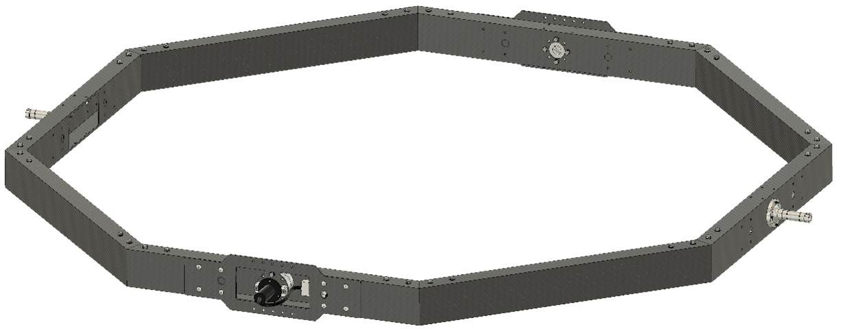
1.2.3 Pitch gimbal
- The octagonal structure is designed to maximize the structural strength of the system while maintaining the less weight possible.
- The gimbal's components are built from either aluminum or carbon fiber.
- The pitch (1) is assembled to the base structure (4) by two low-friction rotary joints. At one of these joints it is located an encoder (6) to measure the pitch angle. While at the opposite end it is located a slip-ring that allows wired communication from the sensors to the FFT Gyroboard.
- All sensors and actuators are connected through an internal wiring system to the FFT Gyroboard, which is a dedicated control board equipped with specialized firmware and drivers for USB communication to a PC.
- The pitch gimbal (1) is the supporting structure of the roll gimbal (2).
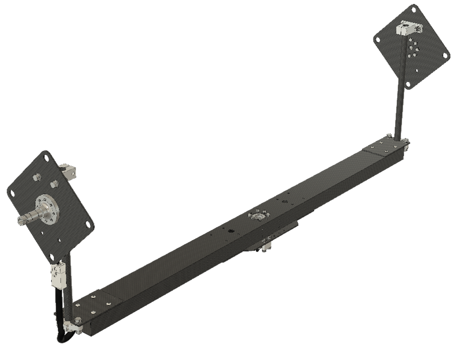
1.2.4 Roll gimbal
The roll gimbal is made of either aluminum or carbon fiber and is attached to two sliding tubes connected to the pitch gimbal (1) by rotary joints. The sliding tubes enable the system to adjust the height of the platform, in order to align the rotation center of the multi-rotor to the rotation center of the FFT GYRO system. In one of these joints, the encoder (7) is located to measure the roll angle, while at the opposite end a slip-ring allows wired communication.
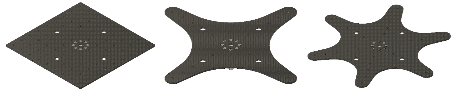
1.2.5 Yaw gimbal
1.2.5.1 Yaw Gimbal in 250-800 series.
Sizes between 250 and 800 include three different plates for your preference. Holes in the plates enable to install grips to mount a drone.
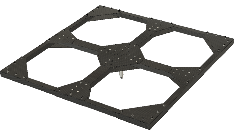
1.2.5.2 Yaw Gimbal in 1000-1500 and 2000 series.
Sizes between 1000 and 2000 support larger and heavier drones, this requires a stronger frame. The yaw gimbal (8) is built with carbon fiber tubes and plates.
1.2.5 FFT Gyroboard
- The FFT GYRO G4.0 electronic system is composed of 5 PCBs in total, 3 of them are connected directly to the sensors(or actuators) and which send the data to the main board, 1 is meant to help with the data communication support as a signal splitter, and there is 1 main data acquisition board which is in charge of processing the data acquired by the sensors.
- The 3 PCBs connected to the sensors are also used to connect and make use of dynamixel servomotors, and depending of the configuration (motors or encoders mounted) the data is sent to the main board using a particular communication protocol, which are automatically detected by the main board.
- Once the main board receives the data, these is post processed and finally sent to the USB using serial communication protocol.
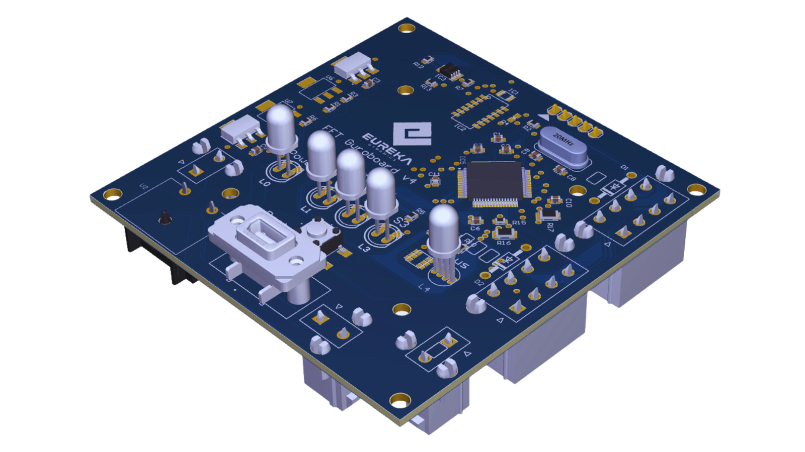
- This main data acquisition board is the FFT Gyro Main PCB.
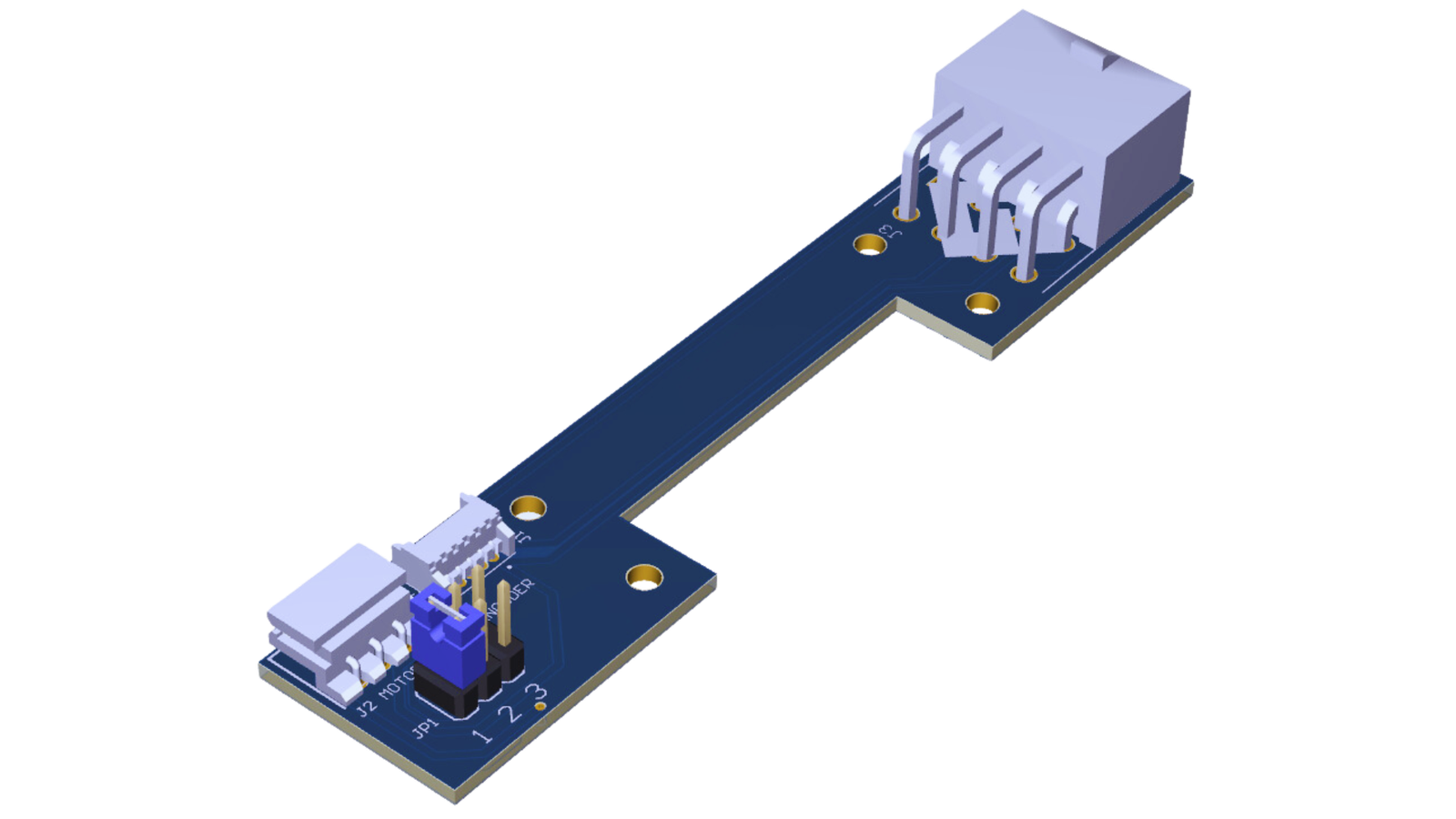
- The boards which are used to connect sensors and motors is called FFT Gyro 2ME PCB.
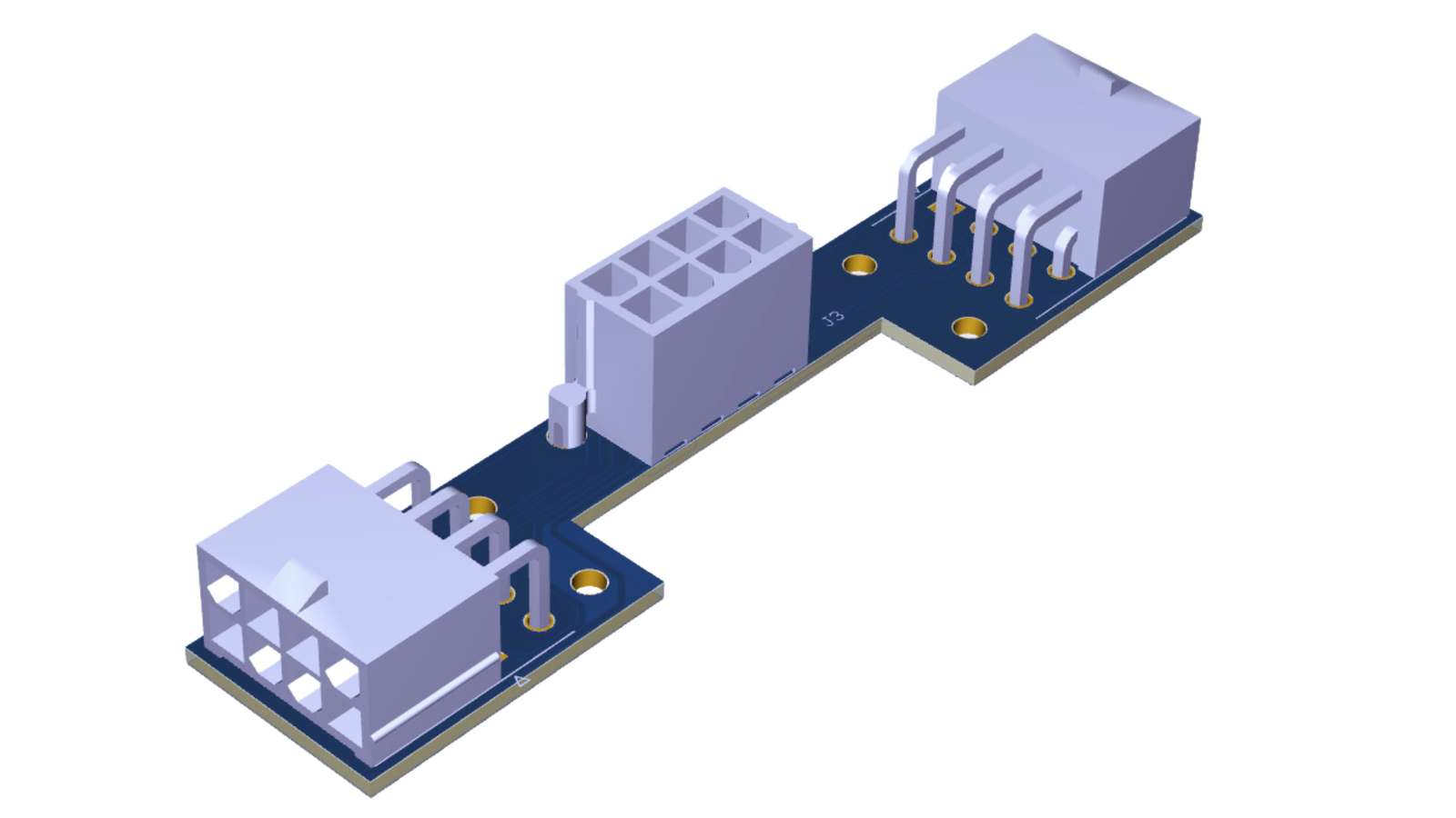
-
The board which is used to split the communication signals is FFT Gyro 122 PCB.
-
The system can be used with an open-source, multi-platform and very simple interface called FFT GYRO Test Tool located at the oficial git repository, and which we will describe in more depth in a later section.
- To download the FFT GYRO Test Tool, visit https://gitlab.com/eurekadynamics/fft-gyro
- MATLAB/Simulink sample programs are also included in the FFT GYRO System oficial repository.
Note
- For customized application development, please refer to the communication protocol section, in which you can find the details of the protocol's packet used by matlab samples code and the FFT Gyro Test Tool, and which you can replicate using any programming language framework that allows you to open a serial communication port.
1.3 Dimensions and main parameters
In this section, the main dimensions and parameters of the FFT GYRO G4.0 system are presented. Dimensions are expressed using the International System of Units (SI). The FFT GYRO’s frame is composed of aluminum or carbon fiber. The material selection allows a rigid structure, safe enough to support the drone, and light enough to minimize the inertia effects on the performance of the UAV. To accommodate different drone sizes and types, the FFT GYRO G4.0 comes in multiple sizes. Each size is designed to support drones within the same category (similar size and weight). Based on standard commercial drone size-to-weight ratios, the available series include: 250, 450, 600, 800, 1000, 1200, 1500, and 2000. Below are the key dimensions and parameters for each series.
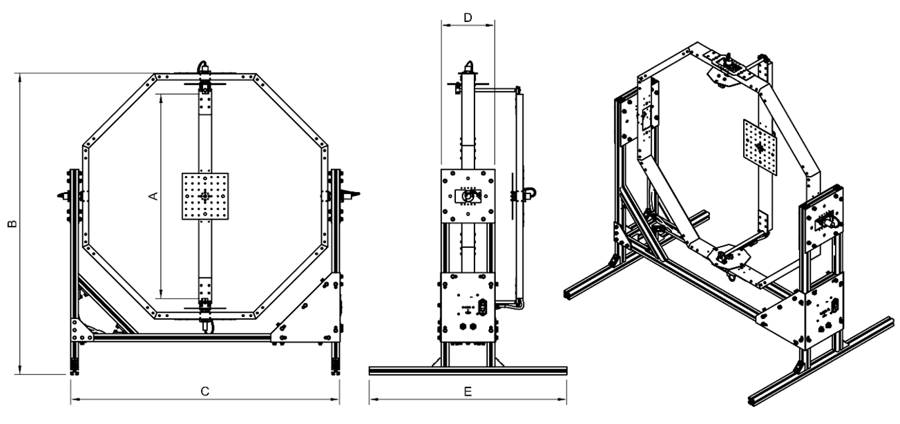
250-800 SERIES
| 250-800 SERIES | FFT GYRO 250 | FFT GYRO 450 | FFT GYRO 600 | FFT GYRO 800 |
|---|---|---|---|---|
| A | 502 mm | 802 mm | 1002 mm | 1252 mm |
| B | 883 mm | 1183 mm | 1383 mm | 1633 mm |
| C | 754 mm | 1054 mm | 1254 mm | 1504 mm |
| D | 210 mm | 210 mm | 210 mm | 210 mm |
| Compatible multi-rotor sizes | 100 mm to 250 mm rotor-to-rotor distance or up to 450 mm drone's outer diameter with unfolded propellers. | 250 mm to 450 mm rotor-to-rotor distance or up to 750 mm drone's outer diameter with unfolded propellers. | 450 mm to 600 mm rotor-to-rotor distance or up to 1000 mm drone's outer diameter with unfolded propellers. | 600 mm to 800 mm rotor-to-rotor distance or up to 1200 mm drone's outer diameter with unfolded propellers. |
| Roll, pitch, and yaw range | 360° (multi-rotations). | 360° (multi-rotations). | 360° (multi-rotations). | 360° (multi-rotations). |
1000-1500 SERIES
| 1000-1500 SERIES | FFT GYRO 1000 | FFT GYRO 1200 | FFT GYRO 1500 |
|---|---|---|---|
| A | 1501 mm | 1801 mm | 2201 mm |
| B | 1823 mm | 2123 mm | 2523 mm |
| C | 1803 mm | 2103 mm | 2503 mm |
| D | 210 mm | 210 mm | 210 mm |
| E | 1655 mm | 1955 mm | 2355 mm |
| Compatible multi-rotor sizes | 800 mm to 1000 mm rotor-to-rotor distance or up to 1500 mm drone's outer diameter with unfolded propellers | 1000 mm to 1200 mm rotor-to-rotor distance or up to 1800 mm drone's outer diameter with unfolded propellers | 1200 mm to 1500 mm rotor-to-rotor distance or up to 2050 mm drone's outer diameter with unfolded propellers |
| Roll, pitch, and yaw range | 360° (multi-rotations). | 360° (multi-rotations). | 360° (multi-rotations). |
2000 SERIES
| 2000 SERIES | FFT GYRO 2000 |
|---|---|
| A | 2801 mm |
| B | 3186 mm |
| C | 3179 mm |
| D | 230 mm |
| E | 2977 mm |
| Compatible multi-rotor sizes | 800 mm to 1000 mm rotor-to-rotor distance or up to 1500 mm drone's outer diameter with unfolded propellers |
| Roll, pitch, and yaw range | 360° (multi-rotations). |