5. Using MATLAB
The FFT GYRO system, enables running custom scripts written in MATLAB or Simulink. To run the scripts, some pre-requisites must be met that are explained below.
MATLAB & Simulink
- To run MATLAB Samples (Scripts and Simulink sample)you will need MATLAB 2017 or Higher.
- All provides code samples were tested using 2017 and 2023 on Windows 10 64 bits.
- When using simulink, be sure to open and execute the files indicated as the 2017 version.
5.1 Simulink
- Open MATLAB 2017 or higher.
- Locate the folder ModeloSimulink and within the file's version you want to test, for example the 2017 or 2023 files.
-
All the samples scripts for connecting and fetching data from FFT GYRO System are listed in this folder.
- SimulinkSampleEncoder
- SimulinkSampleMotorJointMode
- SimulinkSampleMotorWheelMode
Sample Files
- SimulinkSampleEncoder: Helps you to test the encoders and get data from them.
- SimulinkSampleMotorJointMode: Helps you test to test the motor in joint mode in which you can control mainly the position.
- SimulinkSampleMotorWheelMode: Helps you test to test the motor in wheel mode in which motors spin freely and you can control the velocity.
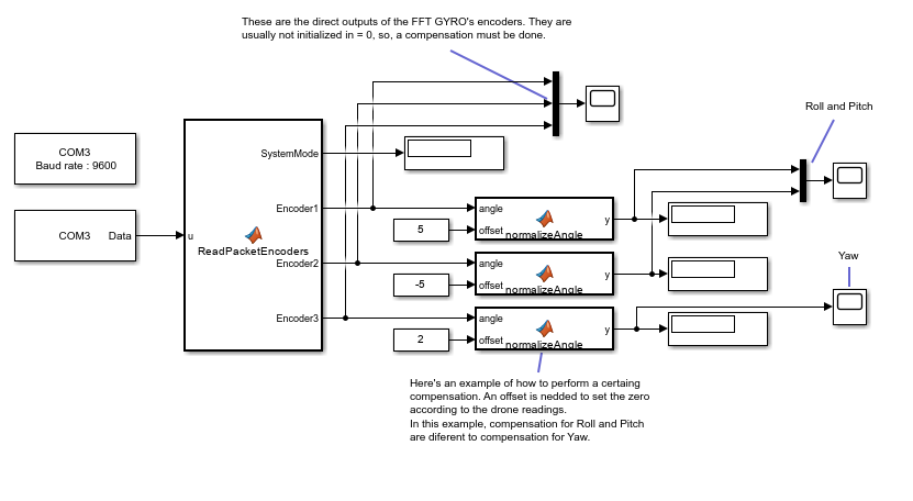
5.1.1 Testing Encoders
- Once the user mount the encoders on the system, this will automatically detect them, and set the encoder operation mode.
- In this mode, the user have few options that can set or transmit to the system, because this mode is mainly used to receive the encoder's data. The data rate frequency is one of the options the user can modify and can be set using the configuration packet, but for now we can work with the predefined data rate of the system, which is 100 ms.
- Open the simulink sample called SimulinkSampleEncoder.slx and lets begin with the setup of the serial communication.
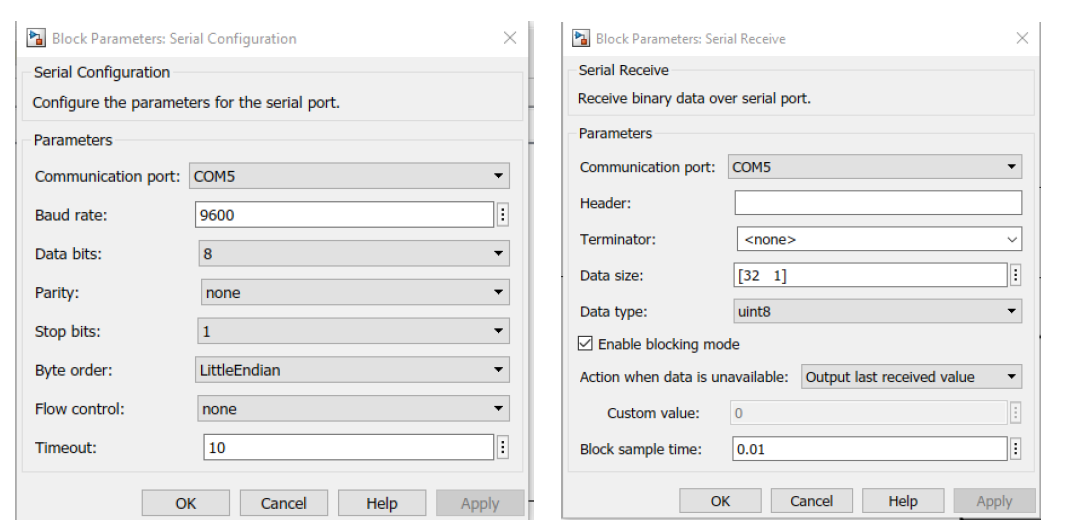
Serial Configuration
- First you need to place a Serial Configuration Block and a Receive Serial Block to open the port and get data through the USB.
- The Serial configuration and Serial Receive Block parameters are shown below.
- It’s important to set correctly as the image below the Data size parameter of the serial receive block and the baudrate and communication port of the serial communication block.
- Configure the serial receive block with data size [32 1].
- Setup the right communication port to which the system is connected(you can see on the device manager of your system, which port name was given to the USB port connected to the FFY Gyro v4)
Encoder Reading in Simulink
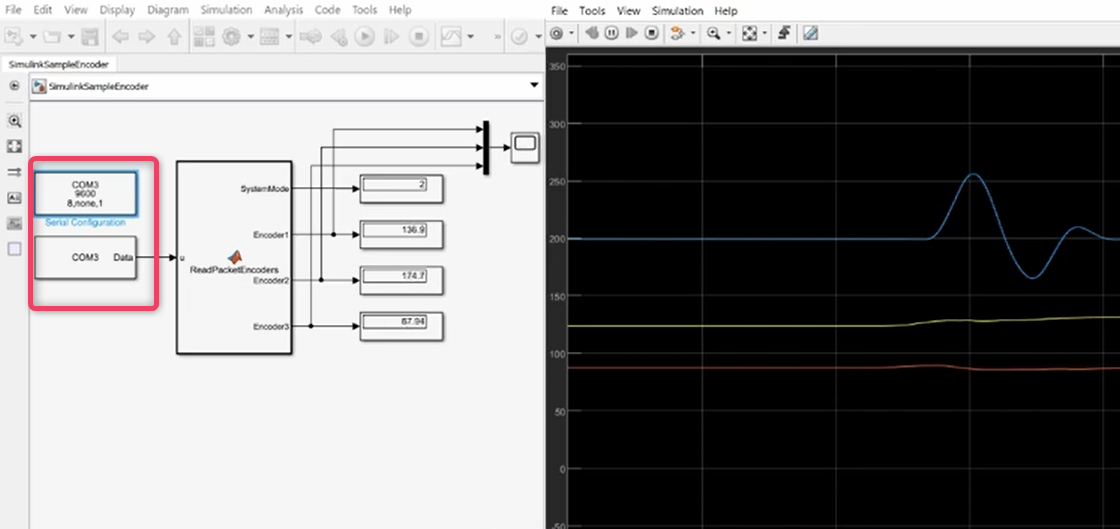
- For encoder readings in Simulink open the SimulinkSampleEncoder.slx file.
- Configure serial configuration block to match your configurations.
- Now, proceed to run the script.
- When running the simulation you can see the output of the ReadPacketEncoder block, changing the values of the 3 different encoders, now you are reading to get some data.
5.1.2 Testing Motors in Joint Mode
- In this mode, users can transmit and receive much more information than in the encoders mode through the COM port.
- Users can configure the data rate to which the packet are received but also modify some other variables since the motors can be commanded to set their velocity, position, torque, and some other options.
- Open the file SimulinkSampleMotorJointMode.slx,and you can some blocks already used such as serial configuration block and serial receive block, both of them are configured the same way as before, but also you can see some aditional blocks placed which are going to be explained below.
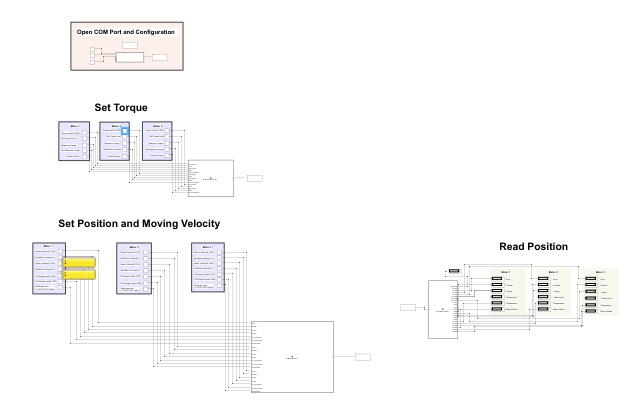
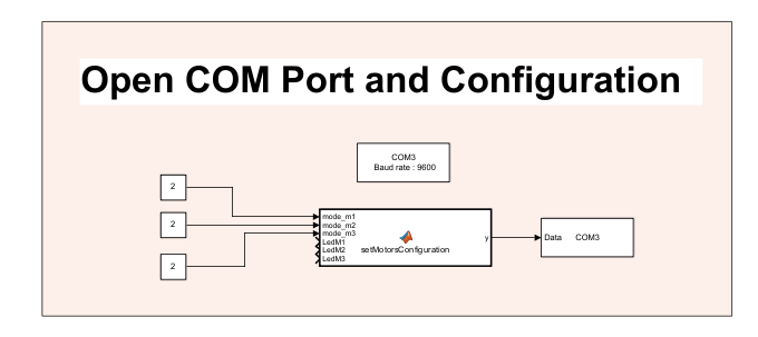
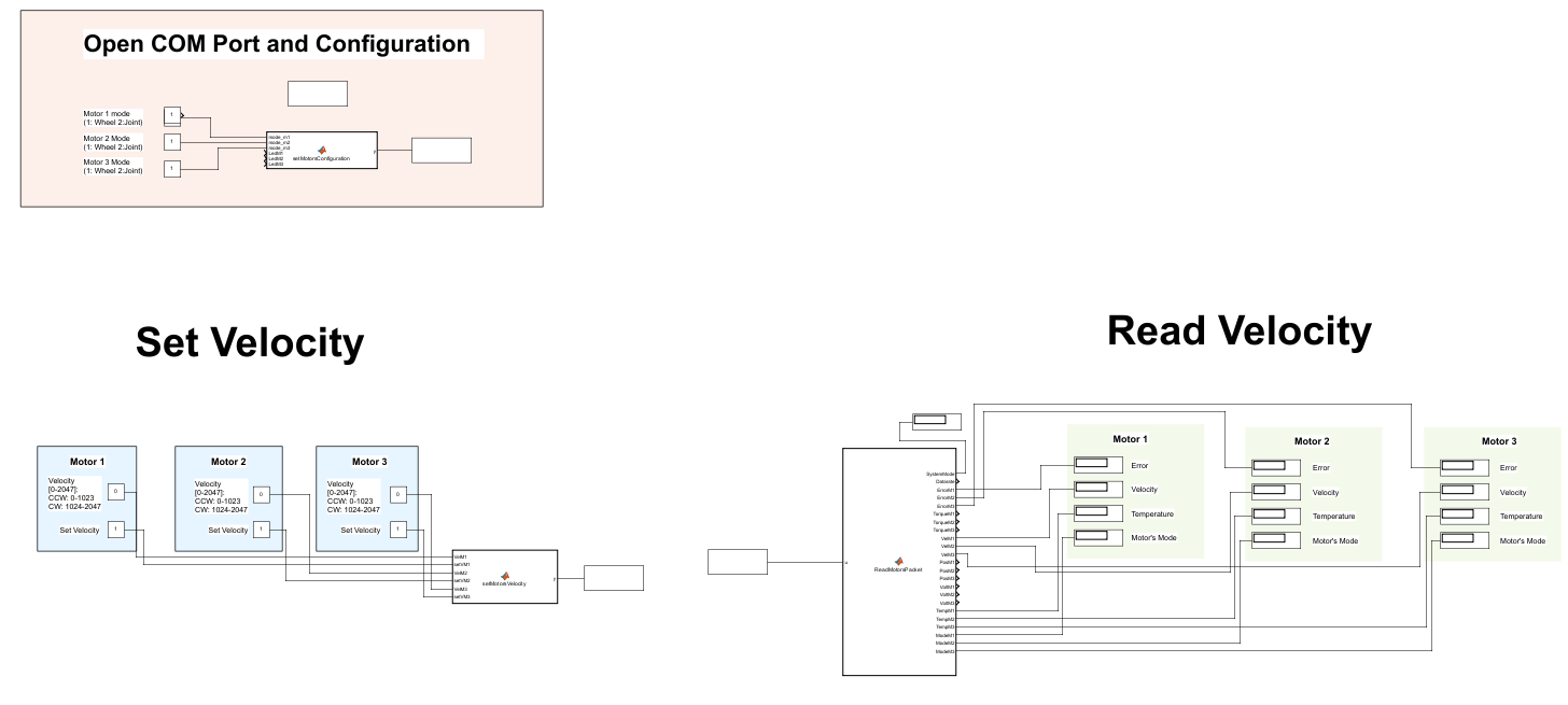
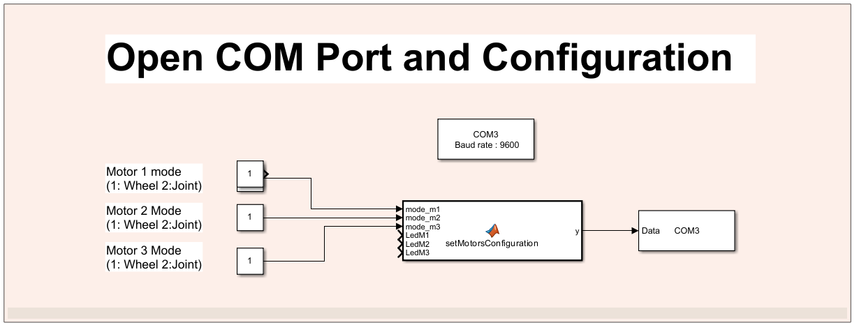
SetMotorsConfiguration Block
- This block is important since this one is responsible of configuring the motors and change between the Joint Mode or Wheel Mode . Write 1 to put the motors in wheel mode and 2 to put them in joint mode. You can also set the status of each motor's LED.
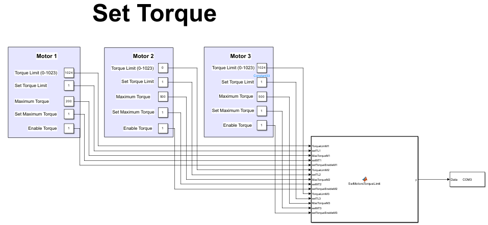
setMotorsTorqueLimit Block
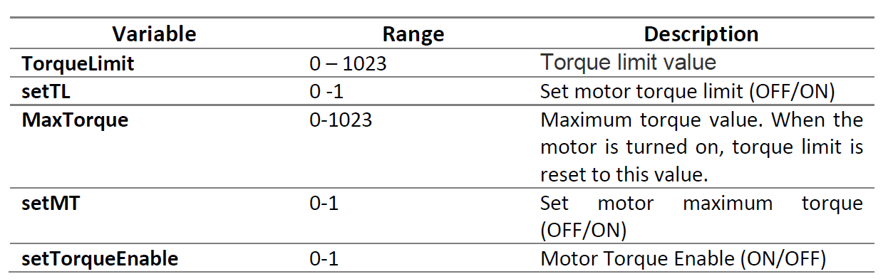
- This block will send a write packet to the motors, setting the torque configuration of each of them. Please note that the values that the different variables can take, will depend on the motors mounted on the system and its specification. FFT Gyro v4 is prepared to handle the different variables values, the same way as specified in the oficial motors specification, provided by dynamixel in the emanuals. The information showed in this manual corresponds to the motors AX-12A, but some other motors by the same manufacturer are compatible with the system, for more information about this values and the meaning of them go to https://emanual.robotis.com/
- In this packet the user can configure torque limit, max torque and torque enable variables of each motor.
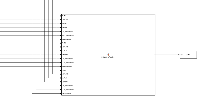
setMotorsPosition Block
-
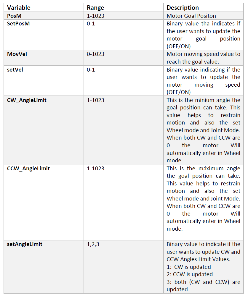
This block has 21 variables, 7 for each motor, to configure different variables of each of them.
-
Refer to the table below for variables, the value range of variables and a short description of each variable. As stated before, this values and variables corresponds directly to the ones available to the motors mounted. For more information about the motor's specification values and limits, we recommend you to take a look to the official motor's documentation in https://emanual.robotis.com/
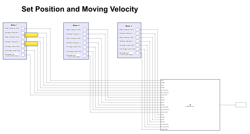
- This block will set the position, moving velocity, and the angle limits (CW and CCW) to each of the motors. Another variable such as Set Motor Position specifies if the motor's variable is going to be set(1) or ignored(0).
- To use this block you will also need a Serial Send as you can see(connected at the end of the setMotorsPosition block), just be sure to specify correctly the communication port.
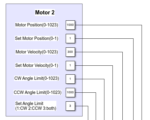
- Some useful information about the variables and the values they can take are shown below, note that this variables corresponds to the motors AX-12A, but they might change if other motor's version are used.
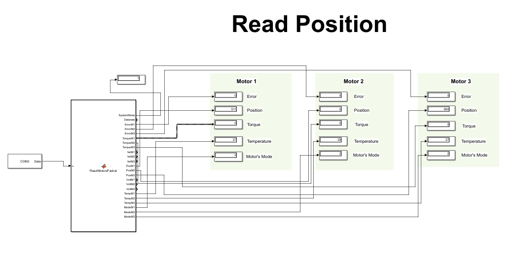
ReadMotorsPacket Block
- To read the incoming data from the motors using simulink you can use the block called ReadMotorsPacket which is going to capture the incoming packets with the information of each motor, such as if there is an error code sent by the motor, the actual position of the motor, the torque, temperature and the motor's mode (Joint or Wheel). Please be sure to specify the right communication port and the data size in the Serial Receive block at the input of the ReadMotorsPacket block.
5.1.3 Testing Motors in Wheel Mode
- In the previous section we explored how to set up the motors in joint mode, and play with the paramteres available to set different positions. But the motors can also be configured as wheels, this is, can spin discretly at the velocity commanded by the user. To delve into this mode, open the matlab/simulink file SimulinkSampleMotorWheelMode.slx.
- In this sample file you will see some familiar blocks such as the setMotorsConfiguration , the Serial Communication block and Serial Send block. These blocks have the same function that is, configure the motor's mode, setup the serial communication and send data through the opened serial port.
- But there is a new block called setMotorsVelocity, this block in particular, only configures the velocity of the motors, and has the option to write each one individually setting (or not) the setVelM variable.
- All the motors have their setVelM variable to indicate if the user would like to set them a value (setVelM = 1) or not(setVelM=0).
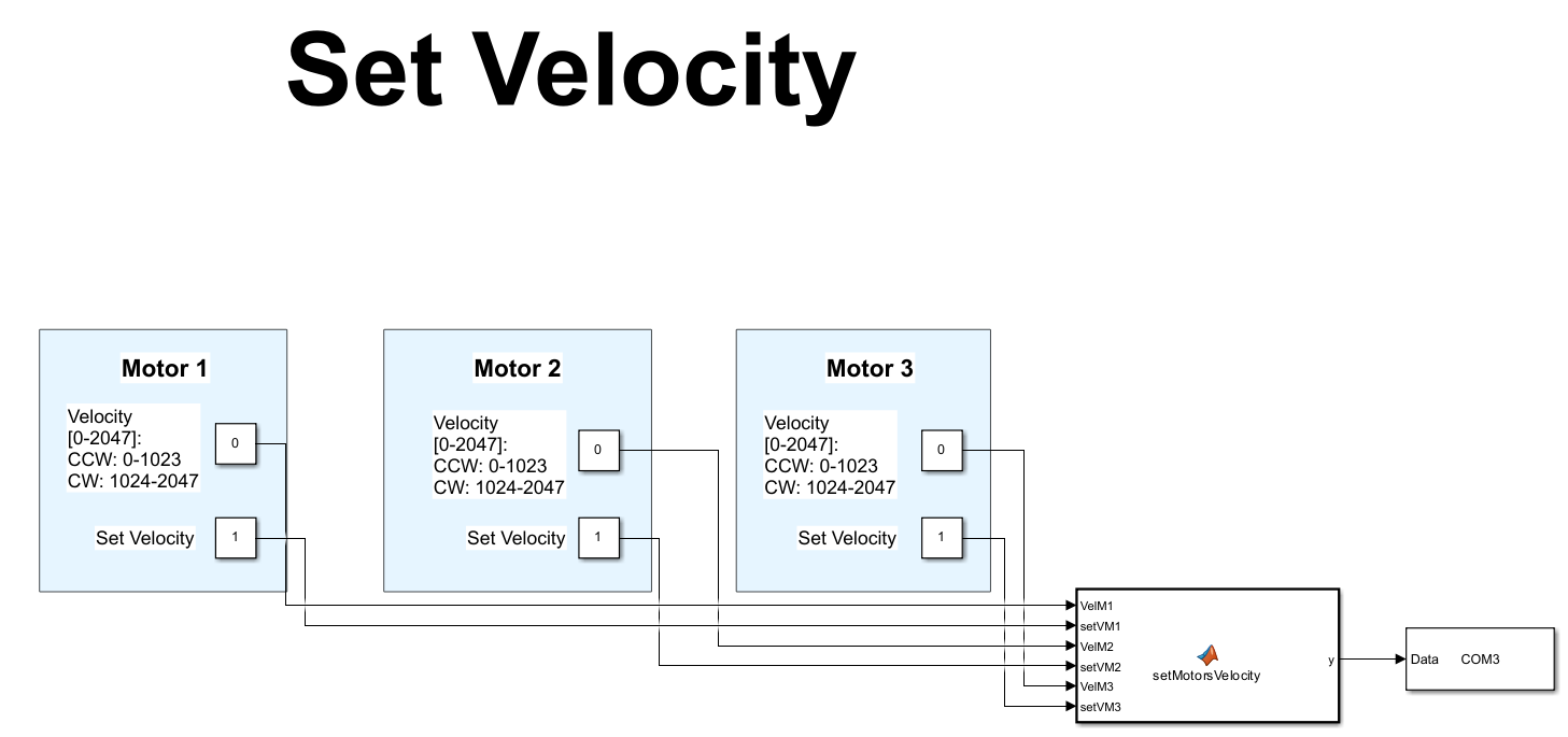
You can see some information defining the limits (the minimum and the maximum value) of the velocity variable of each motor. This specifications corresponds directly to the values defined by the manufacturer to the specific motor model in used. For this example, the motors used are the AX-12A, if you want to delve more into the details of these variables for this motor or any other compatible model, please refer to the official documentation of the motor from the dynamixel manufacturer.
SetMotorsVelocity Block
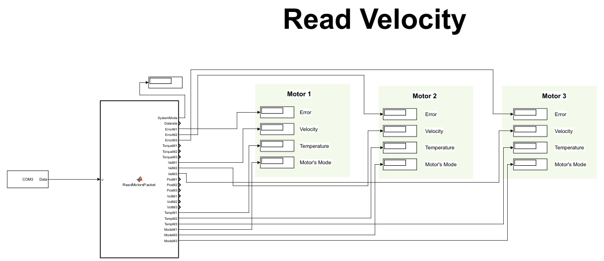
ReadMotorsPacket Block
- This block receives the motor packet and will allow you to know the status of the motors and some other information such as the error code sent by the motors(if any), the actual velocity, the temperature and the actual motor's mode.
5.2 Scripts
You can also connect to the FFT Gyro V4 using some sample scripts that you can later modify to customize them as you wish.
- Open MATLAB 2017 or higher.
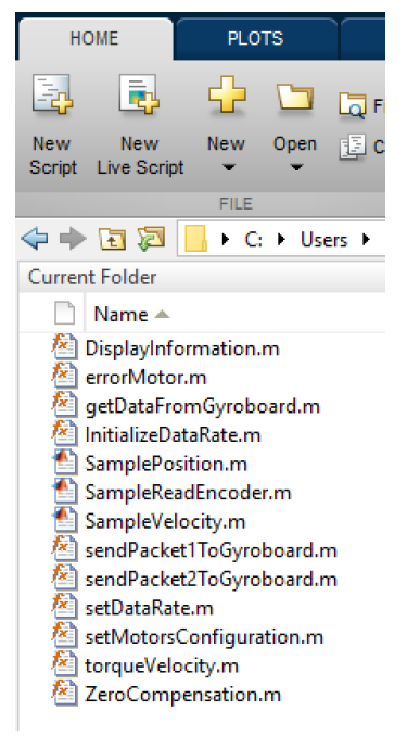
- Locate the folder Sample MATLAB Script .
- All the functions and scripts for connecting and fetching data from FFT GYRO System are listed in this folder.
Sample Files
- SamplePosition: Helps you test and check positioning attributes.
- SampleVelocity: Helps you test and check velocity attributes.
- SampleReadEncoder: Helps you connect and read Encoder values.
5.2.1 Testing Encoders using Scripts
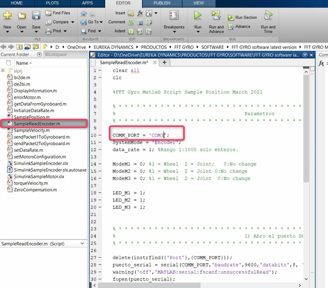
- For encoder readings in MATLAB open the SampleReadEncoder.m file.
- Match the communication ports. If needed, edit the port value to match your configurations.
- Now, proceed to run the script.
5.2.2 Testing Motors in Joint Mode using Scripts
To test the motors in joint mode, you can use one of the two available scripts for MATLAB. These files are .m files and provide a simple example of how to send a position command to the motors when they are used in joint mode.
- SamplePosition(.m): This file provides a simple example of how to send a position command to the motors using the sendPacket2ToGyroboard function. Once all the motors reach the specified position, the program ends.
- SamplePositionRoutine(.m): This file provides a simple routine where a position command is sent every 100 ms, incrementing by 10 each time. Once the position reaches the maximum possible value, it begins to decrement by 10 until it reaches zero. Once the count reaches zero, the program ends.
5.2.3 Testing Motors in Wheel Mode using Scripts
You can also test the motors in wheel mode, where you can send a velocity command to the motors and make them spin. To test this feature, you can use the MATLAB script SampleVelocity.m.
- SampleVelocity(.m): The program will send a specific velocity command to the motors and wait for 10 seconds. Afterward, it will send a zero velocity command and end the program.
5.2.4 More Information about the Scripts Functions
In this section, we provide a more detailed explanation of the functions used in the MATLAB scripts to send commands. All the options and configurations available through these functions are based entirely on specific versions of motors compatible with the FFT Gyro System. The values for variables such as position, velocity, and torque depend on the version of the motors being used.
5.2.4.1 Configuration Function
The function in Matlab is called setMotorsConfiguration, if you want delve into details about how packet is build you can open the function using matlab scripts.
Matlab example
Matlab example
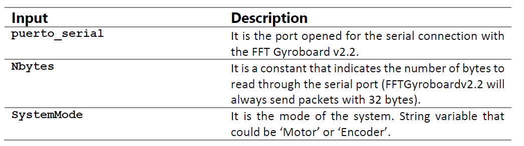
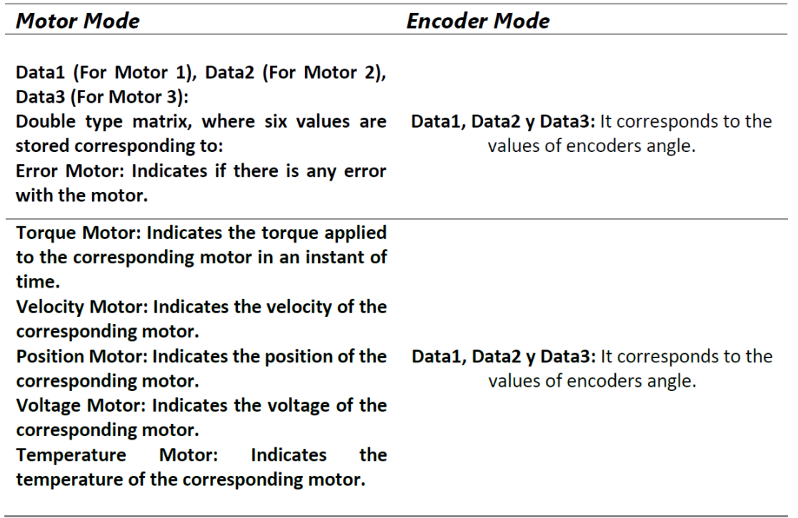
- In Matlab you can make use of the function getDataFromGyroboard and this wil retreive the data from encoders or motors depending on which ones are mounted on the system:
- The input parameters are:
- And the outputs of the function are Data1, Data2, Data3, which depending on the mode(motor or encoder) the meaning will be differente.
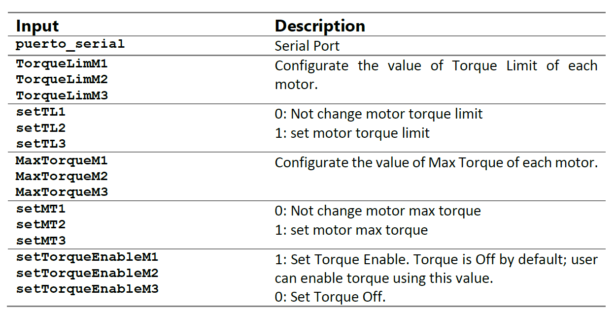
5.2.4.2 Write Type-1 Function
The Type-1 of Write Packet allows modifying the Torque parameters.
Arr = sendPacket1ToGyroboard(
    puerto_serial,TorqueLimM1,setTL1,
    MaxTorqueM1,setMT1,setTorqueEnableM1,
    TorqueLimM2,setTL2,MaxTorqueM2,
    setMT2,setTorqueEnableM2, TorqueLimM3,
    setTL3,MaxTorqueM3,setMT3,setTorqueEnableM3)
Parameter Descriptions
5.2.4.3 Write Type-2 Function
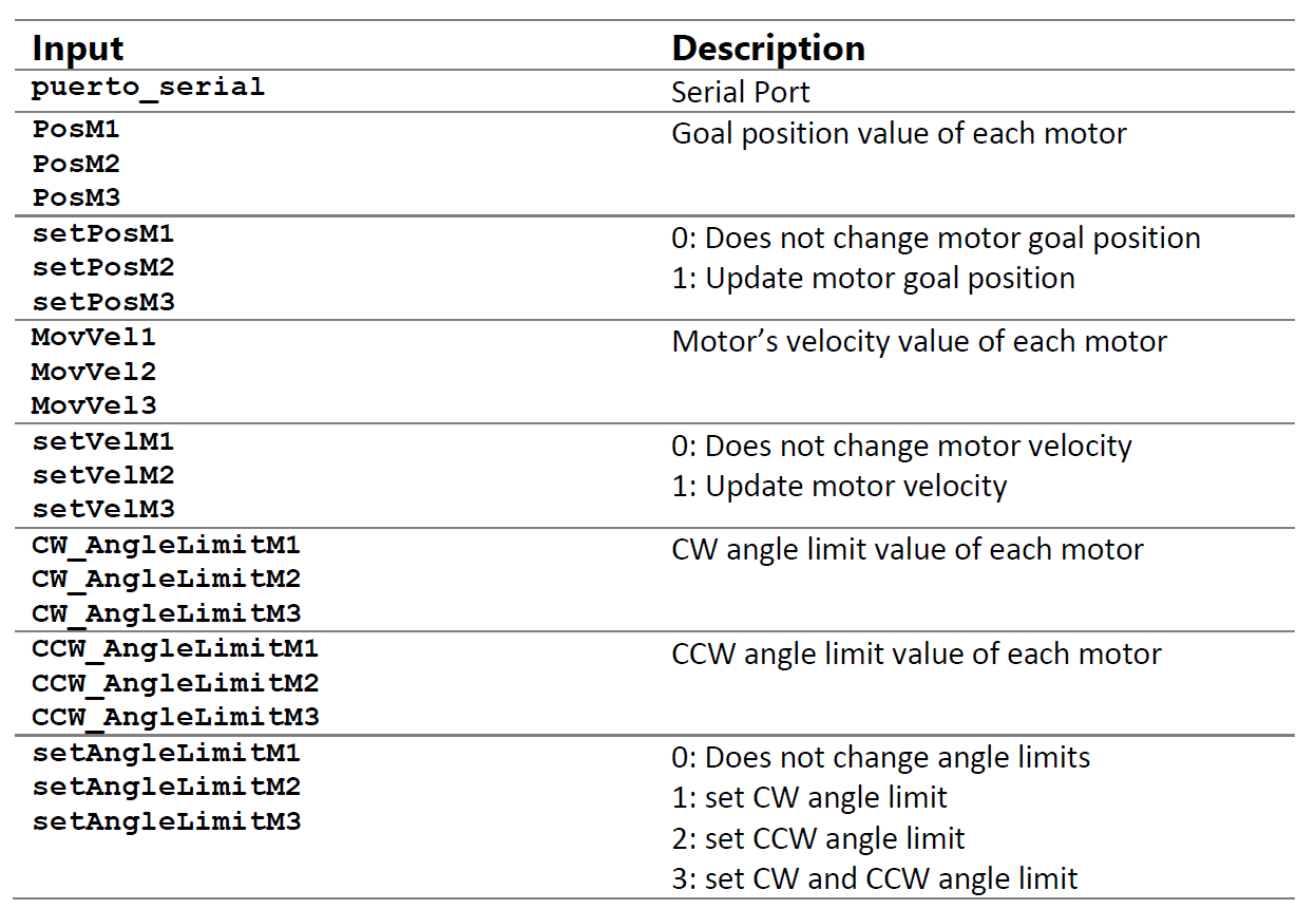
The Type-2 of Write Packet allows modifying position, velocity and limit angle parameters.
Arr = sendPacket2ToGyroboard(
    puerto_serial, PosM1,setPosM1,MovVel1,
    setVelM1,CW_AngleLimitM1,CCW_AngleLimitM1,
    setAngleLimitM1,PosM2,setPosM2,MovVel2,
    setVelM2,CW_AngleLimitM2,CCW_AngleLimitM2,
    setAngleLimitM2,PosM3,setPosM3,
    MovVel3,setVelM3,CW_AngleLimitM3,
    CCW_AngleLimitM3,setAngleLimitM3)
Parameter Descriptions