3. Assembly and Installation
3.1 General considerations
- It is recommended to install the FFT GYRO system in a space with good ventilation.
- It is also recommended to place it on a table with stability and free space on all four sides, so that air can flow easily.
- It is recommended to have an electrical contact (100-250VAC, 50-60 HZ) close to where the system is going to be installed, as well as a place where to place a PC and its peripherals.
3.2 Unpacking and Assembling
The system is shipped unassembled. The package content and the steps to fully assemble the FFT GYRO G4.0 are linked below, or request them to us at info@eurekadynamics.com
- FFT GYRO G4.0 —series 250-800 Assembly Manual —or watch the video
- FFT GYRO G4.0 —series 1000-1500 Assembly Manual —or watch the video.
- FFT GYRO G4.0 —series 2000 Assembly Manual —or watch the video.
Information
- Click to View the Instruction Manual in PDF
- For quick set up an installation procedure, please refer to the youtube video "Assembly Guide and Setup".
Voltage and Surge Protection
- It is necessary to place a regulation and overload protection device to protect the integrity of the electronic system of the FFT GYRO G4.0.
- When using the system with a multi-rotor, the introduction of any object into the internal area of the system is not allowed, for the safety of everyone and the device.
3.3 Component verification
Once the system is installed, evaluate the mobility of the three degrees of freedom by unlocking the gimbals and manually moving each one without being connected to a power supply. This is just to verify the free rotation of G1, G2 and G3. Each gimbal must rotate smoothly in both ways and should not have any physical obstruction that prevents free rotation (test multi-roll movements in both directions).
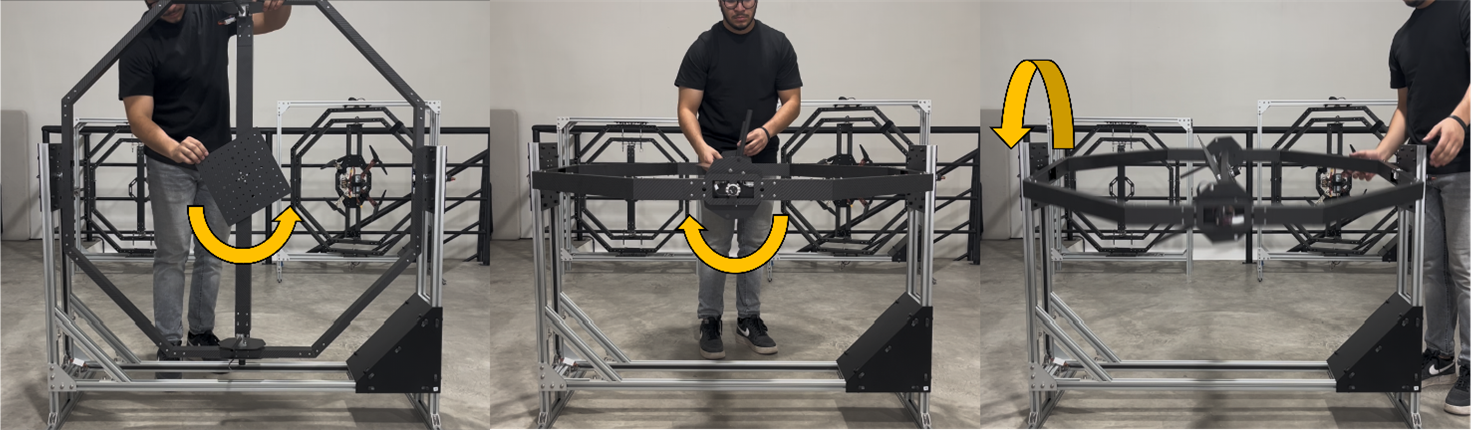
If the three degrees of freedom can move freely, then the system is suitable for use. Otherwise, if any of the gimbal structures presents an obstruction to movement, please contact us at info@eurekadynamics.com
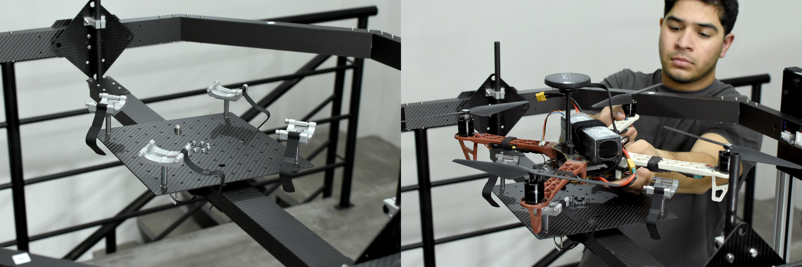
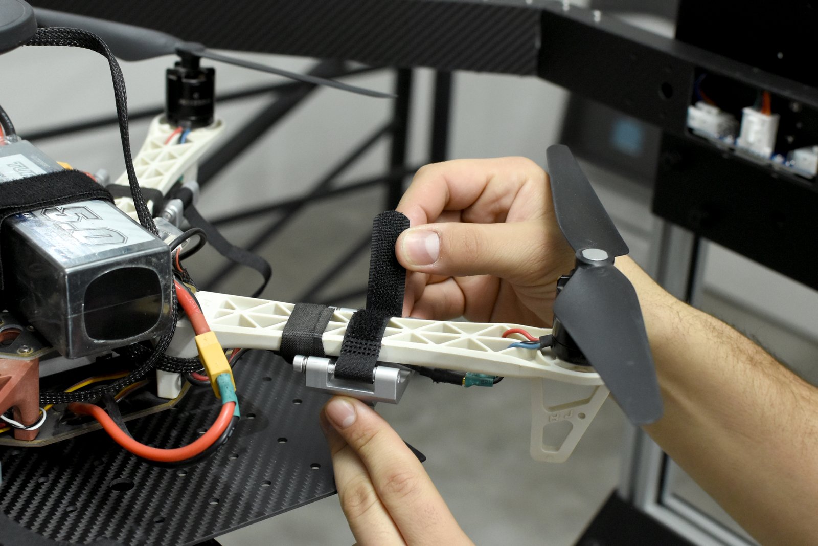
3.4 Multi-rotor installation in FFT GYRO base.
Start by installing the included grip standoffs to the YAW plate using a 3mm Allen key. Once secured, position the drone to align each rotor arm with a grip, and use the included Velcro straps to firmly fasten in place. To learn how to balance a drone in the FFT GYRO G4.0 please watch the video below.
3.5 Motor Installation Steps
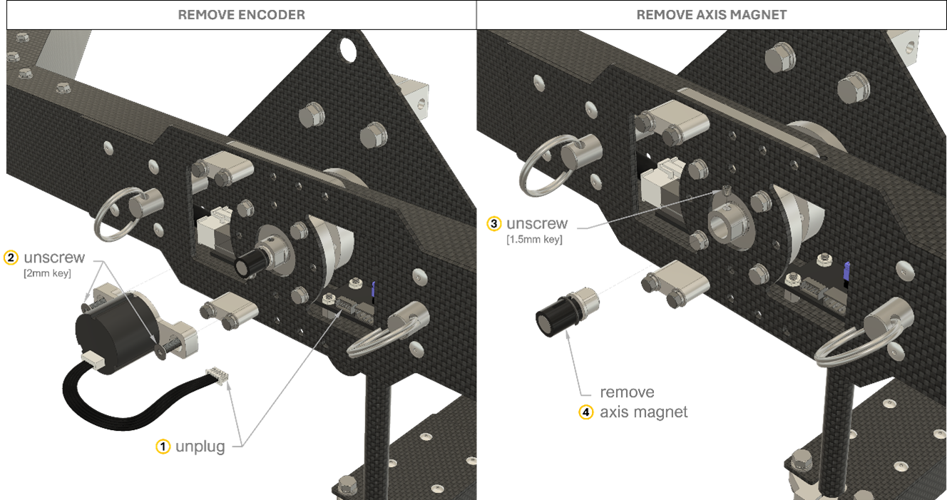
First, align the gimbals at home position (0° labels should match) and lock rotation with locking pins. Uninstall encoders by disconnecting the encoder cable carefully. Use a 2mm Allen key to remove the encoder mount. Use a 1.5mm key to unscrew the set screw, and finally, remove the axis magnet. Repeat the same process with every encoder.
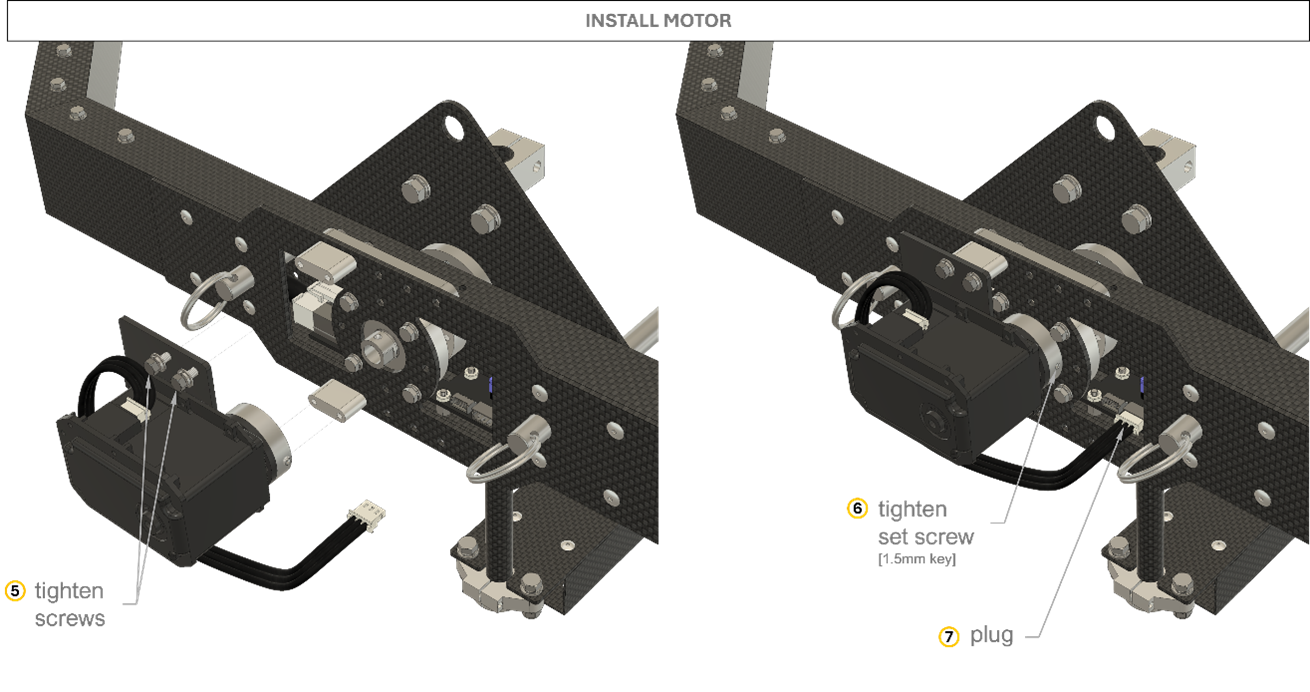
Install the motor, every tag must match. Once the motor is installed, adjust the motor disk set screw using a 1.5mm key, the set screw must be very tight. Finally, connect the motor cable.
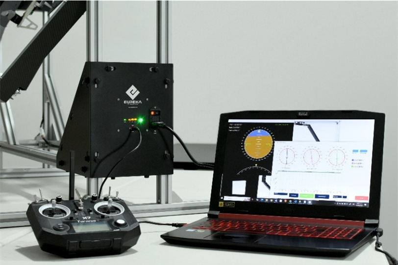
3.6 Software Settings
This section outlines the requirements and general considerations related to the software that interfaces with the FFT GYRO system.
The communication between the FFT Gyroboard and the PC is established via a USB serial connection. The board uses a generic USB driver that is compatible with most operating systems and does not require proprietary software.
Eureka Dynamics has developed a graphical interface called the FFT GYRO Test Tool, designed specifically for interacting with the FFT GYRO system. This tool is compatible with Windows, macOS, and Linux platforms. Due to the simplicity of the communication protocol, the system requirements are minimal.
Minimum System Requirements for FFT GYRO Test Tool:
- Operating System: Windows 7 or higher, macOS X 10.8.5 or higher, or Ubuntu Linux 12.04 or higher
- Memory: At least 2 GB of RAM
- Storage: At least 1 GB of available disk space
- Ports: One available USB 2.0 port
Once your system meets these requirements, you can proceed with the physical connection.
Connect the mini-USB end of the cable to the FFT Gyroboard. Connect the standard USB end to an available USB port on your PC.
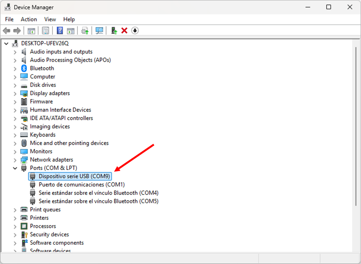
On Windows, you can confirm that the device has been properly recognized by opening the Device Manager. Navigate to the Ports (COM & LPT) section and identify which COM port has been assigned to the FFT Gyroboard. In this example, we will assume the system has been assigned to COM9.
In the next section we will delve more into the FFT Gyro Test Tool, and how to use it.