4. Using FFT GYRO Test Tool
The FFT GYRO Test Tool helps connect a PC with the FFT GYRO System and assists users in easily testing the system. The tool provides a variety of commands and charts to control and visualize the incoming data. The FFT GYRO Test Tool is a graphical user interface (GUI) developed using Processing 3 and Java, consisting of three windows that display different information about the system.
Processing
- Processing 4.0 version or higher is required to run the FFT GYRO Test Tool.
Compatible OS Versions
- Windows: Windows 7 or higher
- Mac OS: MacOS X 10.8 or higher
- Linux: Ubuntu version 14.04 or higher
4.1 Software Setup
To start using the FFT Gyro Test Tool, a few essential steps must be completed. By following the instructions below, you'll be able to easily configure the FFT GYRO Test Tool on your computer and begin interacting with your FFT GYRO hardware.
4.1.1 Requirements
The software has minimal processing requirements due to its simple communication protocol. Requirements for the FFT GYRO Test tool are listed below:
| Requirement | Specification |
|---|---|
| Operating System | Windows 7 and above, MacOS X 10.8 and above, or Ubuntu Linux 14.04 or above |
| RAM | 2GB RAM (Minimum) |
| Storage | 1 GB Free Storage Space |
| USB Port | 1 USB 2.0 or higher port |
Exe files were compiled for different operating systems such as windows 32 and 64 bytes, and Linux with different kernel architectures. Please verify the distribution and architecture of your computer, and stick to the recommendations made here to ensure a proper operation. If any issue comes up with an exe file, we suggest you to open the program as a developer with Processing, compile the code, and make the exe file using the option File/Export Application.
To run the FFT GYRO Test Tool as a developer is necessary to install Processing 3.0 version or higher, and before running the code, it is also mandatory to install the graphical library controlP5 available in Tools/Add Tool/Libraries. This will be explained later.
4.1.2 Download the FFT GYRO Test Tool
Eureka Dynamics has developed an intuitive graphical interface called the FFT GYRO Test Tool for interacting with the FFT GYRO board. This tool is fully compatible with Windows, macOS, and Linux operating systems.
- Click to download the FFT GYRO Test Tool (Download the zip file as image below)
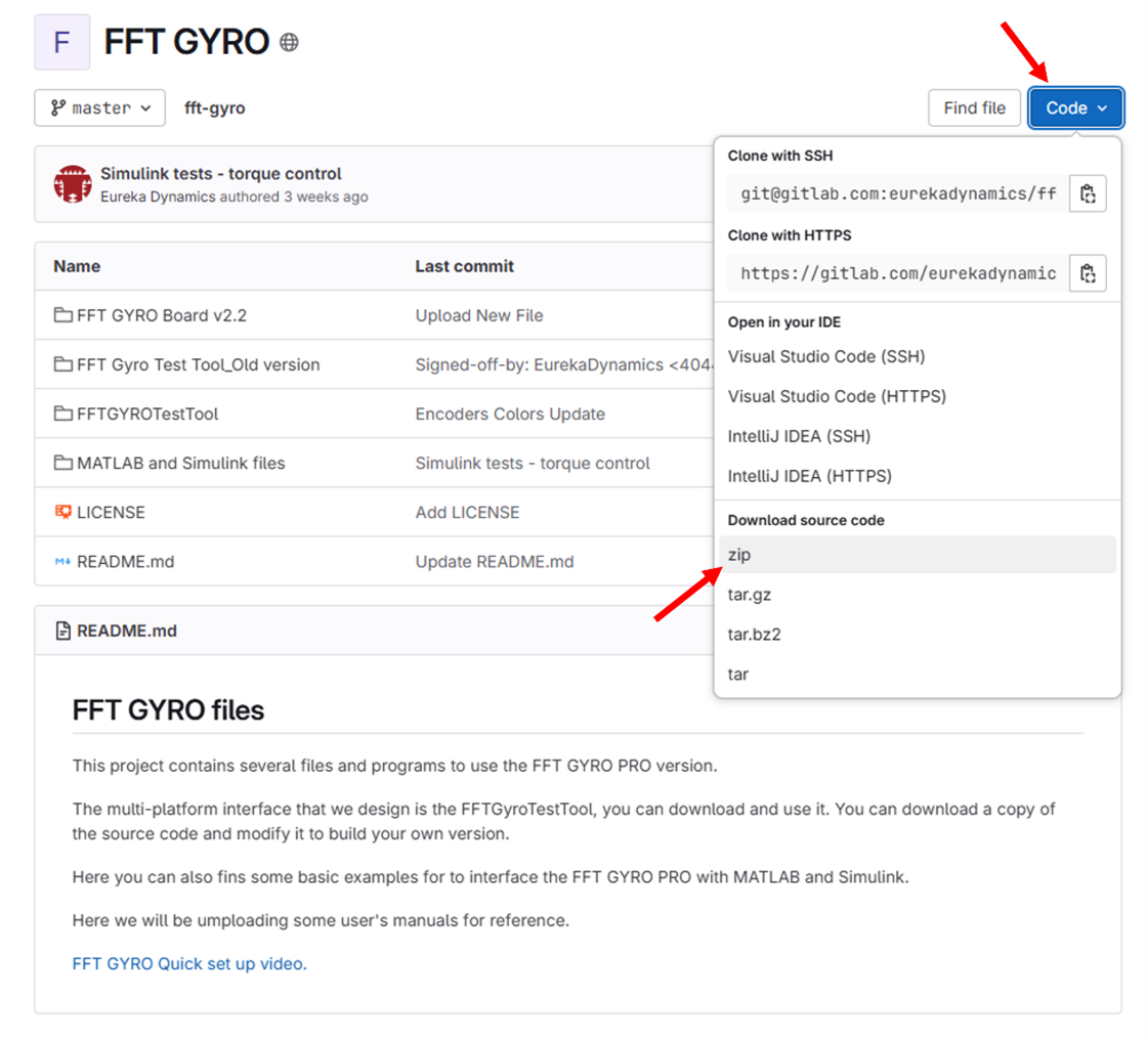
- Decompress the file and access the folder, named “fft-gyro-master”.
- Once inside the folder, go to the following direction (for this example, we will assume that the designated operating system is Windows 11): fft-gyro-master\FFTGYROTestTool\windows-amd64
- Locate the exe file called “FFTGYROTestTool”, select it, and press enter.
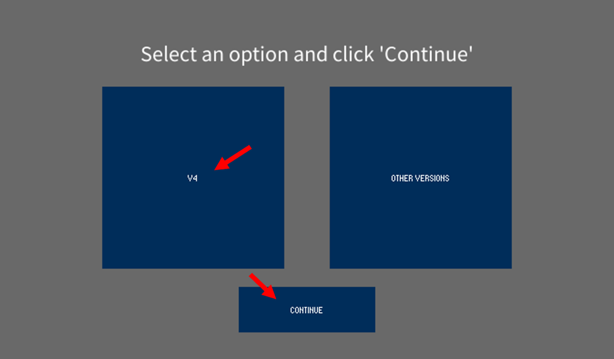
- As the file opens, a menu will display two options. Click option V4, then click CONTINUE.
- Three windows will be displayed. Locate the Main Control Window, it should be totally blank, as in figure 18.
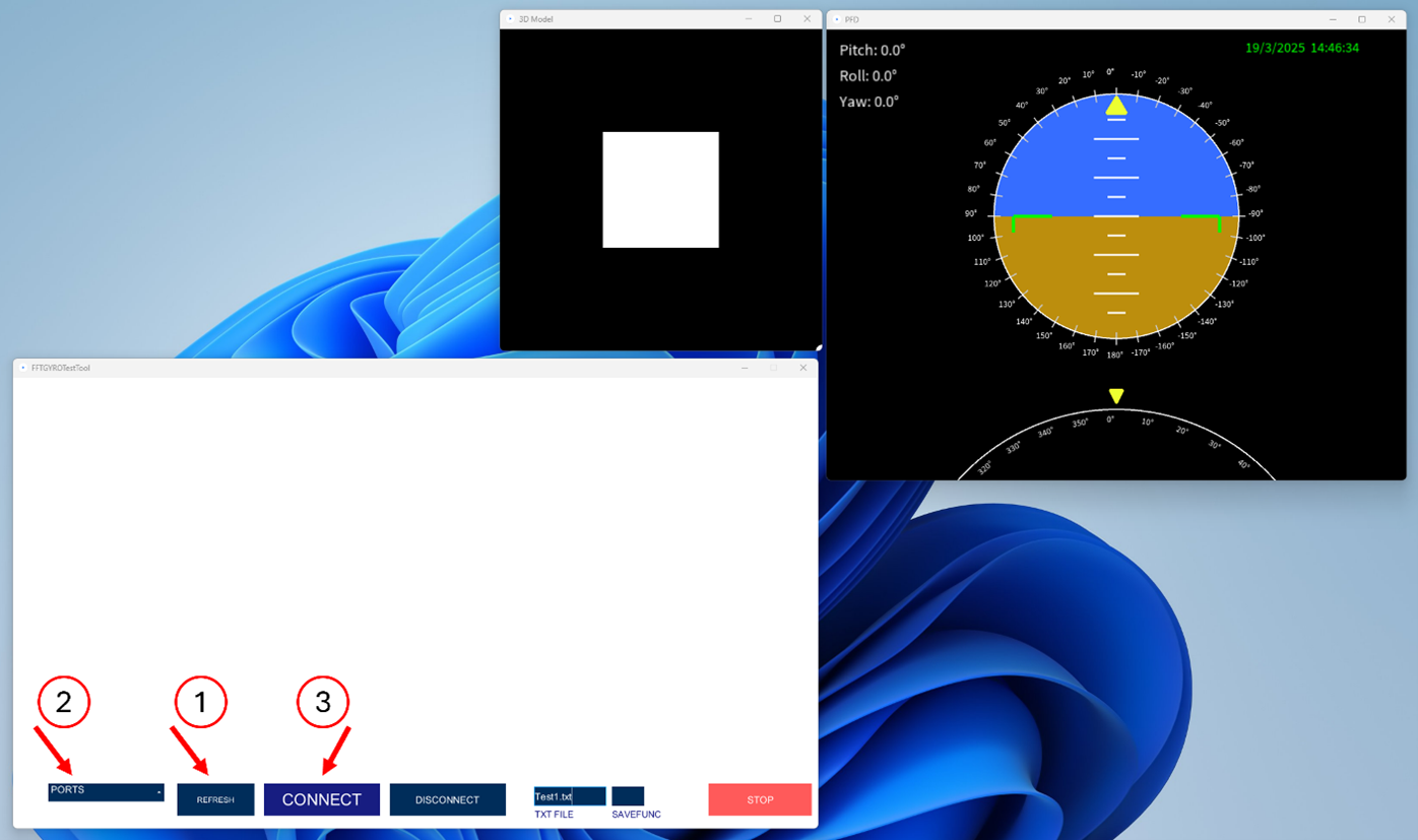
Next, plug the FFT GYRO (using the included USB cable) to the computer, push the REFRESH button to update the ports available on the list. On that list, select the port corresponding to the FFT GYRO, and click CONNECT. If everything is ok, you will see the CONNECT button turn green, and the label will display CONNECTED. Now you will be receiving data from the FFT GYRO.
Information
- To run the FFT GYRO Test Tool as a developer, please install Processing 3.0 version or higher.
EXE Files
- EXE files were compiled for different operating systems such as windows 12 and 64 bytes,Mac Os X and Linux with different kernel architectures.
- Verify the OS distribution and architecture of your local system and always comply to recommendations.
- In case of any conflict or issues, Open the program with Processing, compile the code and make the exe file using the option File/Export Application.
4.1.3 Running the FFT GYRO Test Tool
- Connect one end of the mini USD port to the FFT GYRO Board and connect the second end to the PC (which is running the FFT GYro Test Tool).
- The FFT GYRO Board will recognize the connection and the on-board LEDs will turn on to indicate the connection. Refer to the screen below for details.

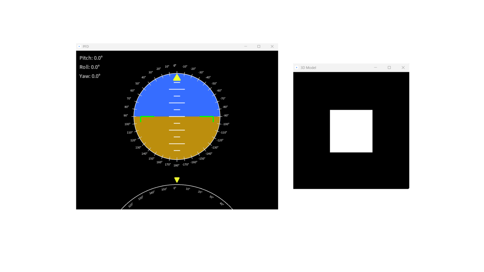
- Run the FFT GYRO Test Tool application and you will see three windows are displayed, two of them are purely for visualization purposes, a Primary Flight Display inspired window and a 3D model of a cube. The other window that have some buttons is the one used for stablish communication with the system. You can notice that this last window that now are refering as the main window, is almost empty.
The other two that serves for visualization, shows figures set with euler angles equals to zero.
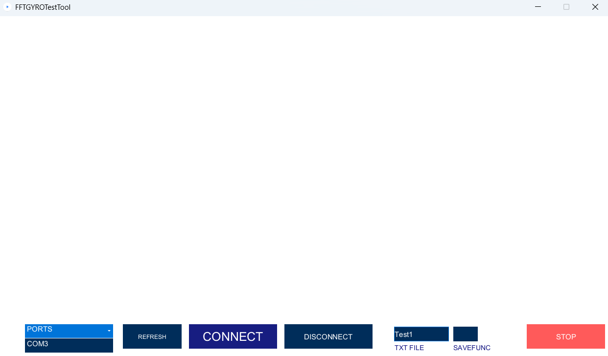
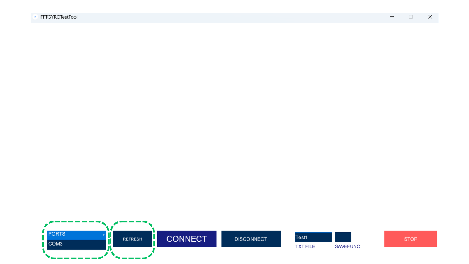
- Now, navigate to the FFT GYRO Test Tool screen and click the REFRESH button to update the ports available on the list.
-
Once the port list is displayed, select the correct port (e.g., COM3 in this example).
-
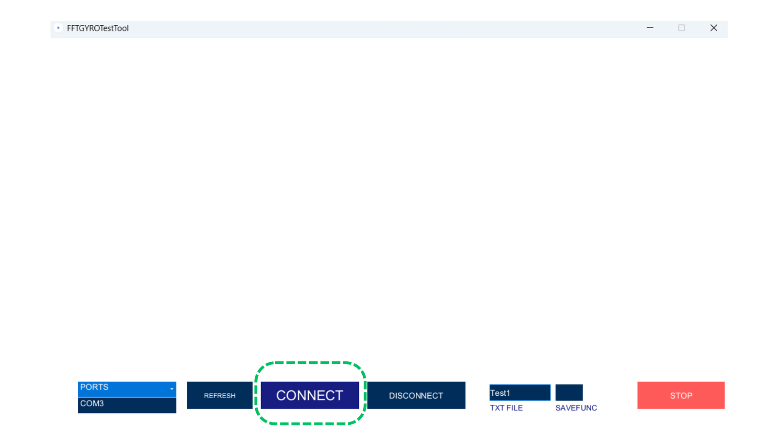
Click Connect.
- Once the port list is displayed, select the correct port (e.g., COM3 in this example).
-
Once the connection is successfully established, the Connect button will turn green, and the label will display CONNECTED. The system will begin receiving data from the FFT GYRO board, indicating that the connection is correct.
-
Initially, the encoder readings may not match those of the onboard sensors. To correct the readings, turn on the multi-rotor in stabilized mode. Wait until stabilization is achieved. Once stabilization is complete, click the Set Home button.
Next, the following screen after establishing a successful communication will depend on whether encoders or motors are connected to the system. In the next section, you will learn more about the different screens, types of commands, and visualization elements on each of them.
Automatic detection mode
The FFT GYRO System will automatically detect what type of element is connected (encoders or motors) and start receiving information, displaying the received data accordingly.
4.2 FFY GYRO Test Tool Screens
4.2.1 Main Screen With Motors
- When motors are mounted on the system, the FFT GYRO Test Tool will display a main interface with a lot of information, but most buttons and controls will be disabled initially. The first thing to do is press the "Press to Start" button to set all the motors in joint mode. This step is essential due to the uncertain state of the motors when first acquired.
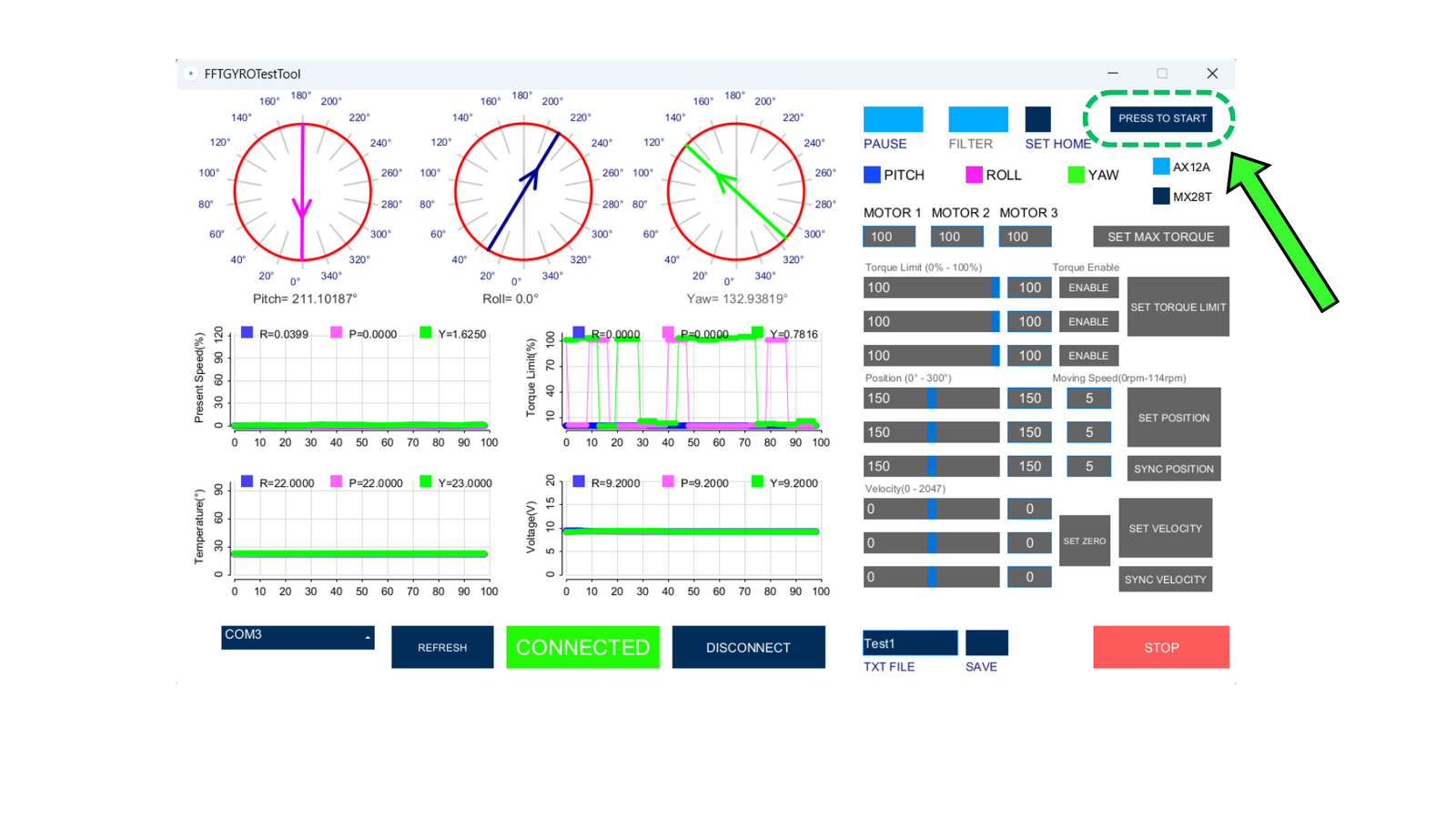
Motors in Joint Mode
- Once you press the button, some of the controls will become available. In joint mode, you can configure each motor's torque and position, including the moving speed.
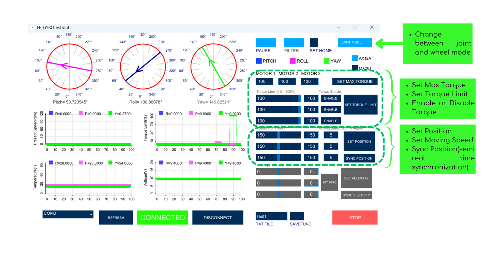
- On the left side of the interface, you will see information displayed such as the absolute position of the encoders, and below, graphs displaying the motor’s temperature, present speed, voltage, and torque limit.
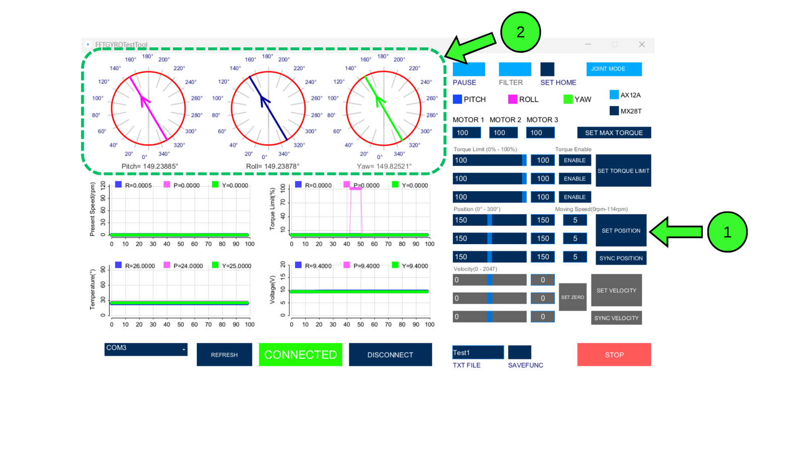
-
To start experimentation, change the position of the motor by clicking the "Set Position" button. The motors will move to the position defined by the slider. These sliders are synchronized with the textbox on each side, so modifying the textbox value will also change the slider to the new value, and vice versa.
-
Feel free to experiment by sending different position values to the system and get familiar with the joint mode interface.
Motors in Wheel Mode
- You can also set the motors to wheel mode, allowing them to spin infinitely, like wheels. To do so, press the Joint Mode button again. This will change the system to Wheel Mode, and you will notice some commands being disabled while others become available.
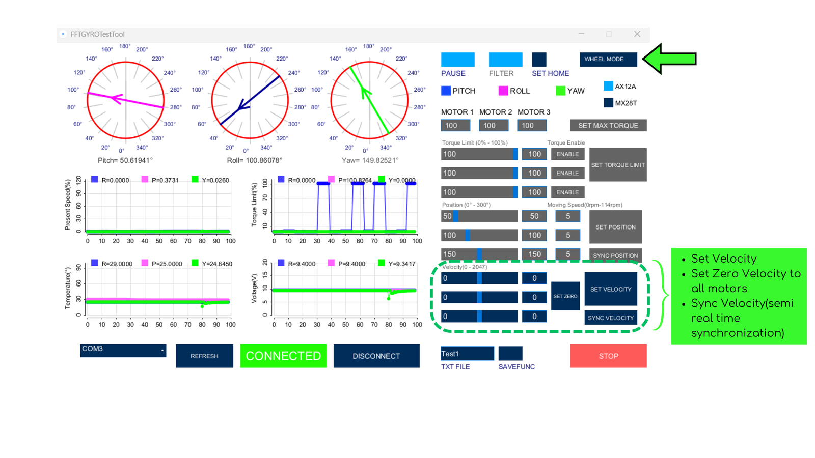
- In wheel mode, you can set the motors' velocity, send zero velocity to all of them with the "Set Zero" button, and control the velocity in semi-real-time using the "Sync Velocity" button and the sliders. Experiment with these commands, but be cautious!
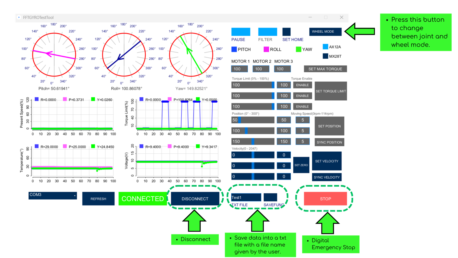
- Other interface commands include:
- The "Disconnect" button, which closes the USB communication.
- A text field to edit the txt output file name.
- The "Save Func" button to start data capturing.
- A virtual "Stop" button to halt the process.
The data is saved by default in a folder called Data, which is created in the same directory where the .exe application is located. The saved data in the txt file is structured as follows when using the motors on the system.
- Timestamp
- Position Motor 1
- Velocity Motor 1
- Torque Motor 1
- Voltage Motor 1
- Temperature Motor 1
- Position Motor 2
- Velocity Motor 2
- Torque Motor 2
- Voltage Motor 2
- Temperature Motor 2
- Position Motor 3
- Velocity Motor 3
- Torque Motor 3
- Voltage Motor 3
- Temperature Motor 3
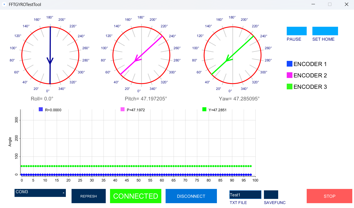
4.2.3 Main Screen With Encoders
- When encoders are connected, the system displays information about the absolute angle of each encoder. In this mode, there are fewer commands compared to motor mode. The following images illustrate the main elements of the graphical user interface that are shown when encoders are connected to the system.
Save Data
-
As with the motor functionalities, there is an option to save data in a txt format. The encoder data is saved into the file with the following structure:
-
Timestamp
- Encoder 1 Data(degrees)
- Encoder 2 Data(degrees)
- Encoder 3 Data(degrees)
Other buttons, such as Disconnect, function the same as in motor mode. The Stop button has no significant role when using encoders, as there are no commands available to send to the encoders—only when using motors.
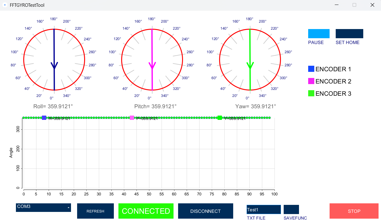
4.3 Sensor Calibration to Relative Zero
-
Initially, the encoder readings will not align with the gyro system's reference frame.
-
To correct this, turn on the multi-rotor in stabilized mode.
-
Wait until stabilization is achieved. Once done, click the Set Home button. This will reset all sensor readings to 0.
JRE Version
- It is recommended to use the Java Runtime Environment i.e. JRE 8.
- Most issues in compiling code or running the exe files are due to wrong version of JRE.