2. FFT GYRO BOARD Technical Specifications
The FFT GYROBOARD is the core of the system, responsible for real-time communication and control of the onboard drone. This section outlines its technical specifications.
2.1 FFT GYRO BOARD Specifications
- The table below lists the principal technical parameters of the FFT GYRO BOARD.
FFT GYRO BOARD Specifications
-
Sensors:
-
Absolute Magnetic Encoders
- 5 Volts
- 12 or 16 bit Resolution
-
Digital motor capable of reading applied torque (12 V Operation)
- SSI Interface
- 12-bit resolution to measure torque
-
-
40 MHZ Clock System
-
Updatable firmware
-
Protocol USB 2.0
-
Auto select mode
- The system automatically selects the mode of operation when three sensors of the same kind are connected.
-
12-15 DC volts operation with external energy source
-
PCB size: 8.0 x 8.0 cm
-
Fuse protection of 3,5 or 10 Amp
-
Acquisition rate
- 100 Hz
-
Emergency Stop
2.2 Schematic Diagram
Below is the schematic diagram of the FFT GYRO BOARD
2.3 LEDs Indicators
Located on the main board, some LEDs provide useful information about the system's overall status.
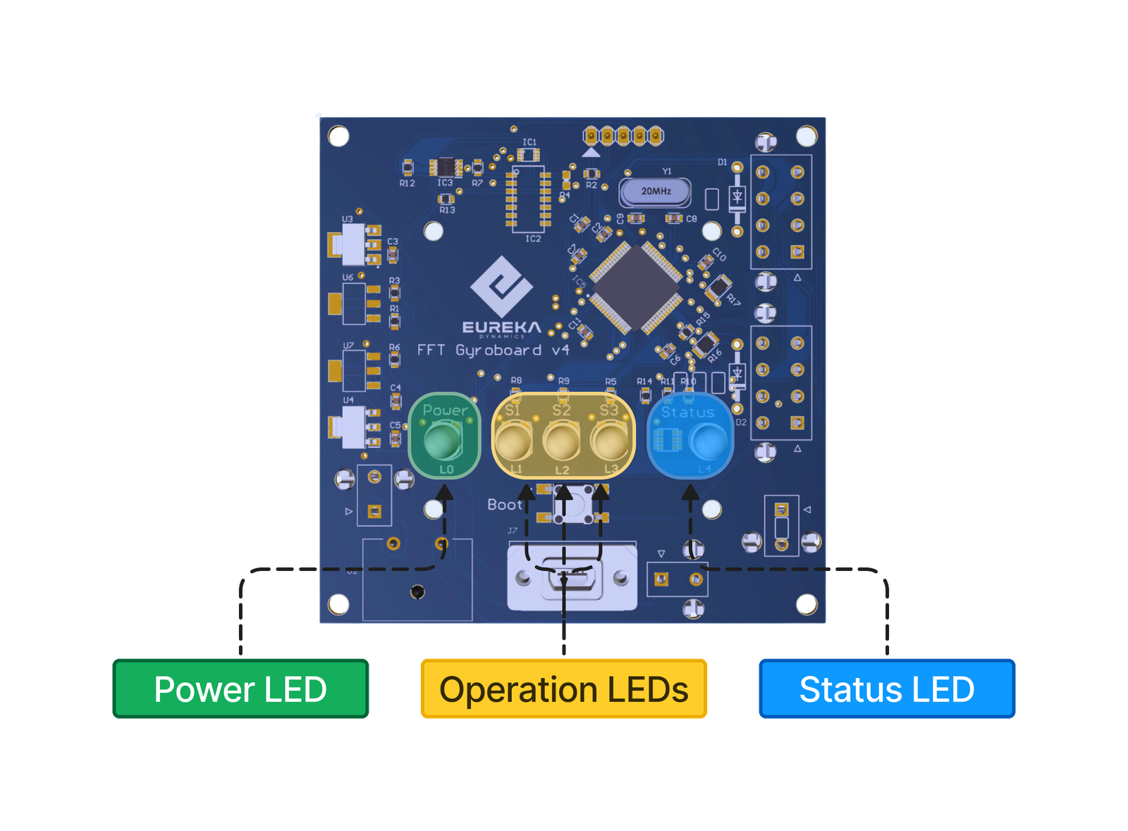
- Power LED: When illuminated solid green, it indicates that the electronic board is powered on.
- Operation LEDs: These three LEDs indicate the status of the sensors/motor connection. Their behavior may change depending on the system’s current state.
- Status LED: his LED shows the general status of the system, such as whether it is in standby mode or experiencing any errors. More information about the possible system states is provided below.
2.4 LED Indications and Explanations
The five LEDs are used to communicate different types of messages or information to the user. Most of them, such as the Status LED and the Operation LEDs, follow specific blink patterns or color changes to indicate system activity. Below, the various frequency patterns and Status LED colors are explained.
The Power LED will always remain on when the system is powered up, indicating that the power supply is functioning correctly.
2.4.1 Stand-by Mode
- When the system is powered on, the first check it performs is to verify if there is an active USB connection between the system and the PC. This waiting mode is indicated by the Operation LEDs turning on and off in sequence, one by one. It is highly recommended that all sensors and motors be in place and properly connected when powering on the system.
| Mode | Power LED | Operation LED (One) | Operation LED (Two) | Operation LED (Three) | Status LED |
|---|---|---|---|---|---|
| Connection Standby Mode |
2.4.2 Missing all Sensors/Motors Connection
- When the user turns on the system and, for some reason, all sensors or motors are not detected, the Operation LEDs will begin to blink simultaneously, and the Status LED will turn red.
| Mode | Power LED | Operation LED (One) | Operation LED (Two) | Operation LED (Three) | Status LED |
|---|---|---|---|---|---|
| Connection Standby Mode |
2.4.3 A Sensor/Motor is missing
- When powering on the FFT Gyro System and connecting it to the PC, if there is a communication issue with one or two sensors/encoders, the corresponding Operation LED will turn off to indicate which sensor or motor is experiencing the problem. For example, the following representation shows that Sensor/Motor 1 is having an issue, while Sensor/Motors 2 and 3 are functioning as expected. This type of problem may occur if the main board is unable to establish communication with a particular sensor or motor.
| Mode | Power LED | Operation LED (One) | Operation LED (Two) | Operation LED (Three) | Status LED |
|---|---|---|---|---|---|
| Connection Standby Mode |
In the following example, two of the sensors/motors are not detected by the main FFT Gyroboard.
| Mode | Power LED | Operation LED (One) | Operation LED (Two) | Operation LED (Three) | Status LED |
|---|---|---|---|---|---|
| Connection Standby Mode |
2.4.4 Ready to Work
- When the system is powered on, the USB connection is established, and all sensors/motors are connected and functioning as expected. In this case, the user will see all the Operation LEDs turned on, and the Status LED will be green, as shown in the following table.
| Mode | Power LED | Operation LED (One) | Operation LED (Two) | Operation LED (Three) | Status LED |
|---|---|---|---|---|---|
| Connection Standby Mode |
Once the system is ready to operate, the next step is to open a tool of your choice (such as the FFT Gyro Test Tool, MATLAB, or any custom-developed software) and begin acquiring data.
2.4.5 Boot Mode
The FFT Gyro 4.0 system introduces a new feature that allows users to update the firmware of the main PCB. To enter this mode, known as Boot Mode, the user must press the button located inside the front panel of the structure for 3 seconds. Once activated, the Operation LEDs and the Status LED will blink in a 2-by-2 sequence, as shown in the following figure.
Power LED Operation LED (One) Operation LED (Two) Operation LED (Three) Status LED
Note
- More information about how to enter to this mode, load the HEX file and more, please visit the Bootloader section.
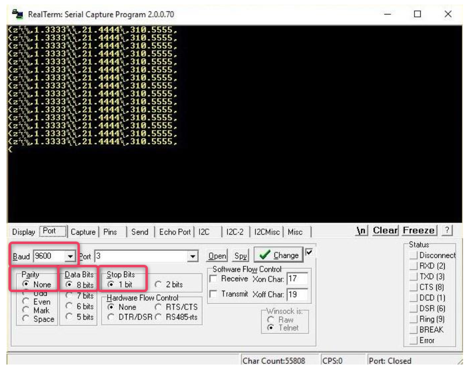
2.5 Serial Communication Specifications
You can open the communication port using any tool or software that supports serial communication, but you will need to build a parser for the data being acquired. Refer to the Packets section to understand how the data is structured and received when using encoders or motors. To start developing you can also use the tools provided by Eureka Dynamics such as FFT Gyro Test Tool and Matlab Samples files, that are ready to start communication with the system.
| Specification | Value to Set |
|---|---|
| Baud Rate | 9600 |
| Data Bits | 8 Bits |
| Parity | None |
| Stop Bits | 1 Bit |
- The screen below shows RealTerm interface which is receiving data in the Encoder Mode.