4. Using FFT GYRO Test Tool (New App)
This section documents the new cross‑platform desktop application for controlling the FFT GYRO system. It is built with Electron + React (Vite) and replaces the legacy Processing/Java tool. Where the new app does not yet have a documented equivalent, the legacy behavior and screens are retained for reference.
4.1 Developer Documentation
4.1.1 Prerequisites
Before setting up the project, install the following:
- Node.js: download from https://nodejs.org/ and verify with
node -vandnpm -v. - Git: download from https://git-scm.com/ and verify with
git --version. - Visual Studio Code (VS Code): https://code.visualstudio.com/.
4.1.2 Clone the Repository
- Open a terminal and navigate to your working directory.
- Clone the repository:
- Change into the repo folder (replace with your folder name if different):
4.1.3 Install Dependencies
From the project root, install packages:
4.1.4 Project Structure
Example structure:
testtool2/
├─ assets/
├─ electron/
├─ public/
├─ src/
├─ package.json
├─ vite.config.ts
├─ tailwind.config.js
├─ tsconfig.json
└─ ...
- src: React components and application logic.
- electron: Electron main process and packaging config.
- public: Static assets (images, models).
4.1.5 Running Locally
- Development server (web):
- Electron development mode:
Other commands:
- Build for production:
npm run build - Run the built app:
npm start - Package installers:
npm run package - Make platform installers:
npm run make
4.1.6 Debugging with VS Code
- Open the project in VS Code:
code . - Recommended extensions: ESLint, Tailwind CSS IntelliSense, Prettier.
- Use the integrated terminal (Ctrl +
) to run commands likenpm run devornpm run electron:dev`.
4.2 User Documentation – Gyro Control App
4.2.1 Installation
Windows
- Download the
.exeinstaller from your supplier/administrator. - Run the installer and follow the steps. If Windows SmartScreen appears, choose More info → Run anyway.
- Launch the app from the Start Menu or Desktop shortcut.
macOS
- Download the
.dmgfile from your supplier/administrator. - Open the
.dmgand drag the app to Applications. - Launch it from Launchpad or Applications. If blocked, go to System Settings → Privacy & Security → Allow Anyway.
4.2.2 Connecting to Your Device (USB Cable)
- Power on the FFT GYRO device and connect it to the computer via the provided USB cable.
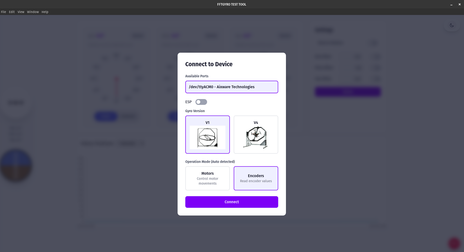
- Open the app; the Connect to Device window appears at startup.
- The available serial port is detected automatically. If none appears, check the cable/driver.
- Select your hardware version: V1 (left) or V4 (right).
- Operation mode selection:
- Motors – control motor movement
- Encoders – read encoder angles
- Note: Over serial/USB, the app automatically detects the correct mode.
Mode selection example:
 6. Click Connect and wait for the status to show Connected before using controls.
4.2.3 Application Interface Overview
Below are examples of common screens you will see:
- Connection modal when the app starts:
- Home screen after connecting to a device:
Ensure the interface matches your version, as updates may introduce changes.
4.3 Features and Screens
The following sections mirror the legacy tool’s behavior and screens until the new UI screenshots are added. Functionality is equivalent where noted.
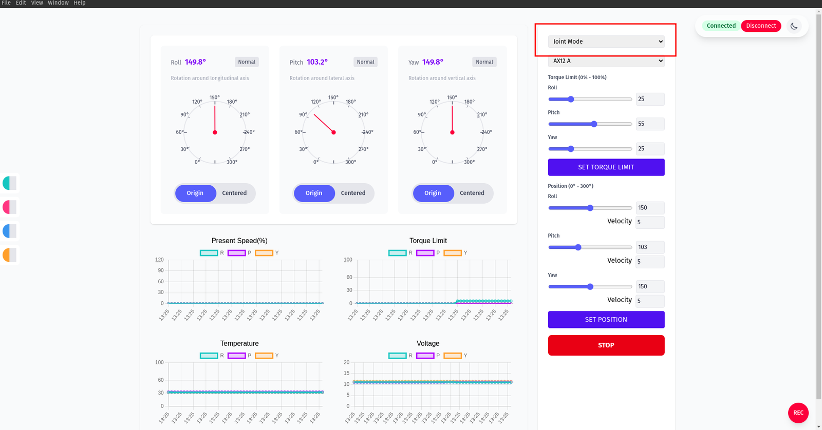
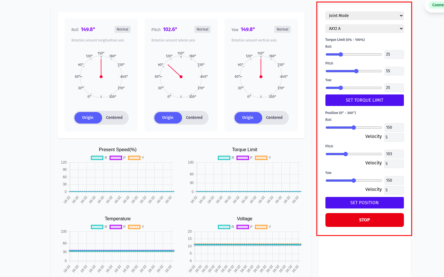
4.3.1 Main Screen With Motors
- When motors are mounted, the interface enables joint or wheel control. Press “Press to Start” to place motors in joint mode (initial safety state varies on first acquisition).
- In joint mode, configure each motor’s torque, position, and moving speed. The interface shows encoder absolute positions and charts for temperature, present speed, voltage, and torque limit.
- Use Set Position to send target positions via sliders or text boxes.
Overall motors view:
Motors in Joint Mode
The right‑hand panel exposes torque limits and position commands per axis. Choose your servo family (e.g., AX12 A) from the dropdown, then adjust sliders and click the respective action buttons.
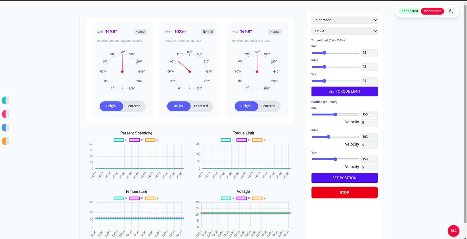
Motors in Wheel Mode
- Toggle Joint Mode again to switch to Wheel Mode (infinite rotation). Set velocities.
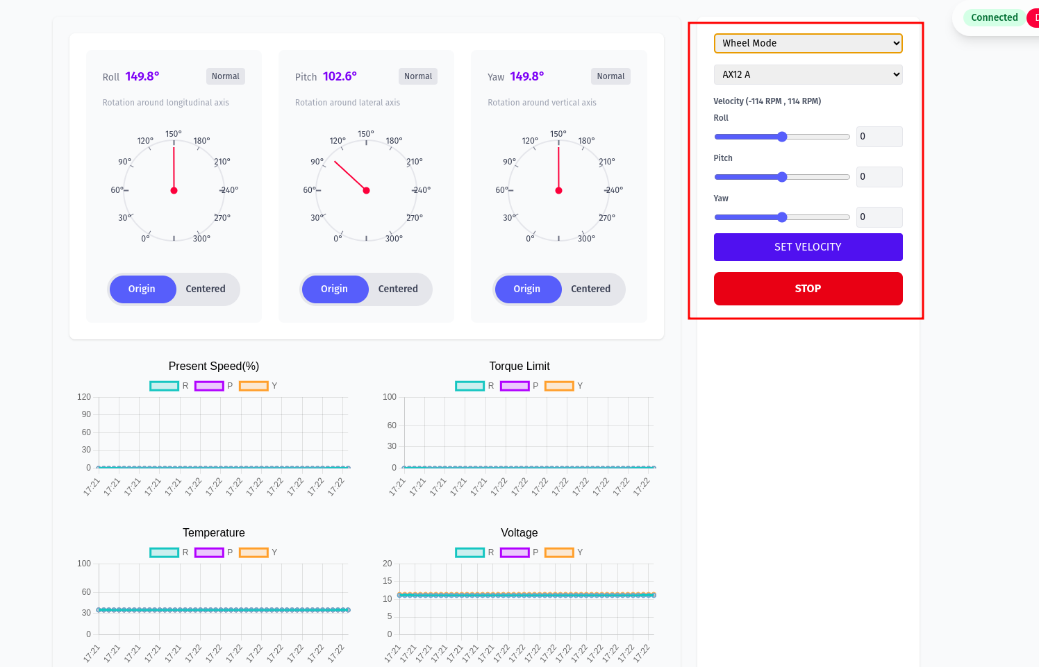
- Other actions: Disconnect (close USB), set output filename, start capture with Save Func, and Stop.
Chart filters and legends example:
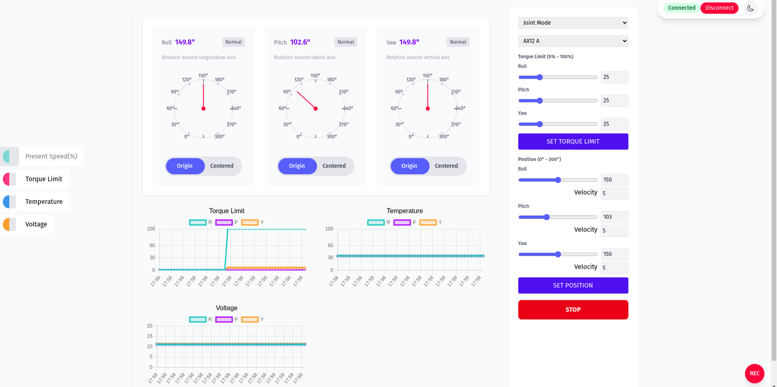
Data is saved by default to a Data folder next to the executable with the following fields when using motors:
- Timestamp
- Position Motor 1
- Velocity Motor 1
- Torque Motor 1
- Voltage Motor 1
- Temperature Motor 1
- Position Motor 2
- Velocity Motor 2
- Torque Motor 2
- Voltage Motor 2
- Temperature Motor 2
- Position Motor 3
- Velocity Motor 3
- Torque Motor 3
- Voltage Motor 3
- Temperature Motor 3
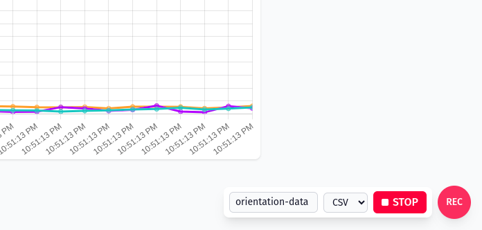
Recording indicator and control (REC button):
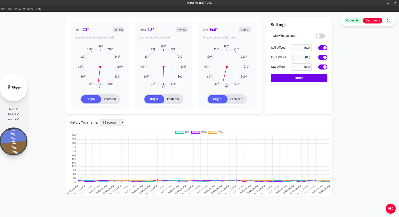
4.3.2 Encoders Screen
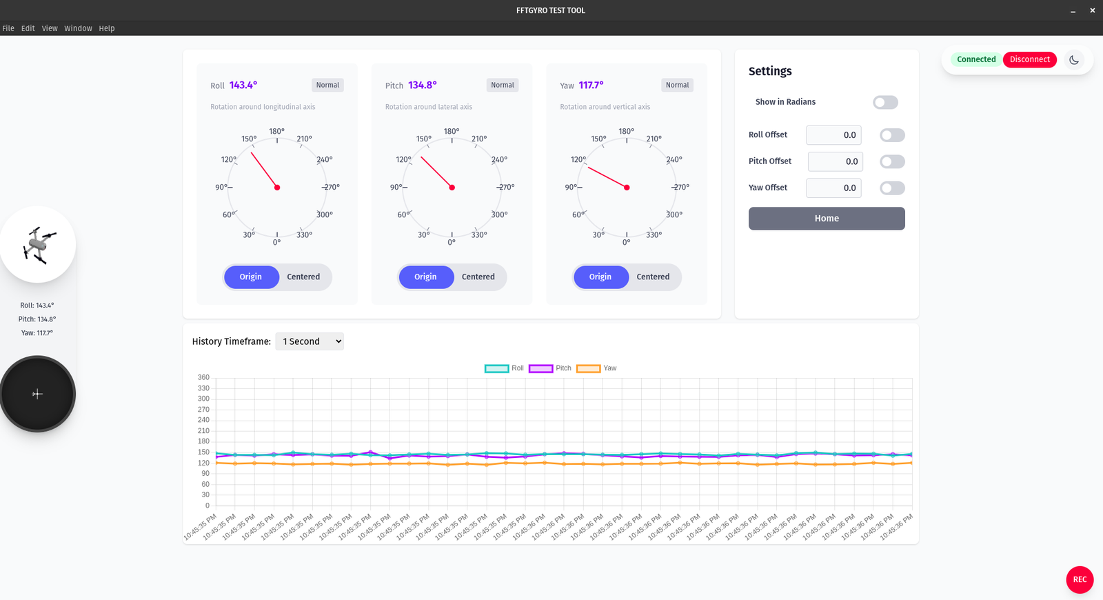
- Three gauges show Roll, Pitch, and Yaw. Each card displays the current angle and a large dial for quick visual reference. A "Normal" badge indicates a healthy data stream.
- Units are in degrees by default. Toggle "Show in Radians" in the Settings panel to switch units across the gauges and the live chart.
- Per‑axis actions under each dial:
- Origin: show angles relative to the device’s absolute reference (mechanical/home origin).
- Centered: set the current reading as a temporary zero to track relative changes from “now”.
- Offsets: use Roll/Pitch/Yaw Offset fields to add a fixed correction (e.g., mounting bias). Enable the adjacent toggle to apply the offset. Applied offsets are reflected in the gauges and the history chart.
- History chart: choose a History Timeframe and watch live traces for Roll (teal), Pitch (magenta), and Yaw (orange). The chart follows the selected window and respects the current unit and offsets.
- Connection controls: the header shows the connection state. Use "Disconnect" to stop streaming from the device.
- Navigation: the Settings panel includes a "Home" button to return to the connection screen.
- Sidebar: a miniature vehicle visualization and quick readouts mirror the three angles for at‑a‑glance status.
- Recording: click the red "REC" button to start/stop logging.
Save Data
When recording in Encoders mode, each row contains:
- Timestamp
- Roll (deg or rad)
- Pitch (deg or rad)
- Yaw (deg or rad)
Notes: - Values reflect any active offsets and the currently selected unit. - Files are saved next to the executable in the Data folder unless changed in your app settings.
4.3.3 Sensor Calibration to Relative Zero
The Home button in the Settings panel allows you to quickly return to the connection screen from any part of the application. This is useful for reconnecting to a device or starting a new session. 1. Initial encoder readings may not align with the gyro’s reference frame. 2. Turn on the multi‑rotor in stabilized mode and wait for stabilization. 3. Click Set Home to reset all sensor readings to 0.